

For wearable projects, having the right sensor module makes all the difference. As you all know, this year’s contest theme is Smart Home and Wearables, so we came up with another sensor module, the MAXREFDES117 optical heart-rate module. This device comes with integrated red and IR LEDs, making it an ideal choice for developers and enthusiasts alike. The MAXREFDES117 optical heart rate module is a compact, low-power sensor designed specifically for wearable health monitoring projects.
CircuitDigest presents the Smart Home & Wearables Project Contest 2025! Win exciting prizes worth up to ₹7,00,000 and receive free development boards through our partnership with DigiKey. For registration, dive into contest details.
This tiny board, perfect for wearable projects, can be placed on a finger or earlobe to accurately detect heart rate. This versatile module works with both Arduino and mbed platforms for quick testing, development, and system integration. That’s why we chose this as one of the development boards for our upcoming Smart Home and Wearable Project Challenge, where you can win prizes up to Rs. 7,00,000. Not only that, you can even win a development board and other exciting goodies just by submitting your project ideas. Measuring just 12.7mm x 12.7mm, this MAXREFDES117 sensor module can accurately detect heart rate and blood oxygen saturation (SpO2) levels when placed on a finger or earlobe.
Be sure to explore the Smart Home and Wearable Project Challenge for complete details and participation guidelines. Now, in this comprehensive guide, let's cover the features of the module, the hardware, methods of interfacing, and examples. Let's see what the MAXREFDES117 Module has to offer.
What's Included in the MAXREFDES117 Package?
Since this is a sensor evaluation module, it’s made to be as small as possible, so no fancy accessories are included. Still, you can check out the unpacking image of this module below.
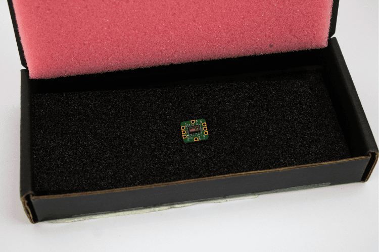
More than just hardware, Analog Devices Inc./Maxim Integrated provides excellent resources to help us get started easily. We’ll see more about that in this article. For now, let’s take a look at what this module comes packed with.
Technical Specifications Overview
| Feature | Specification |
| Board Dimensions | 12.7mm x 12.7mm (0.5in x 0.5in) |
| Power Consumption | 1.5 mA at 3.3V (Ultra-low power) |
| Input Voltage Range | 2V to 5.5V (Multiple voltage support) |
| Communication Protocol | I2C Interface |
| Sensor Type | Optical (Red & IR LEDs) |
| Primary IC | MAX30102 Heart Rate/SpO2 Sensor |
MAXREFDES117 Module: Key Features and Specifications
The MAXREFDES117 reference design is a low-power optical heart-rate module complete with integrated red and IR LEDs, along with a power supply. Perfectly suited for low-power wearable projects, here’s the list of features and benefits:
Features & Benefits
- Heart-Rate Monitor and Pulse Oximeter Sensor in LED Reflective Solution
- Highly-integrated, small-size sensor - 12.7mm x 12.7mm (0.5in x 0.5in) Board Size
- Non-chest-based heart rate/SpO2 detection
- Ultra-low power consumption (1.5 mA at 3.3 V input)
- Multiple Input Voltage Level (2v to 5.5v)
- Device Drivers
- Free Algorithm
- Example C Source Code for Arduino and mbed Platforms
Application of MAXREFDES117
Below are some of the possible applications of this module.
| Wearable Health Devices: | Ideal for smartwatches, fitness trackers, and health monitoring patches. |
| Medical Monitoring: | Suitable for continuous monitoring of heart rate and oxygen saturation levels in patients. |
| DIY Projects: | Useful for hobbyists and developers creating custom health monitoring solutions. |
| Educational Purposes: | A valuable tool for learning about optical sensing and biomedical instrumentation. |
MAXREFDES117 Hardware Architecture
The MAXREFDES117 optical heart rate module utilises a sophisticated two-sided PCB design with strategic component placement for maximum space efficiency. Now that you’re familiar with the features of the module, let’s take a detailed look at the hardware. In general, this module is a two-sided PCB with components soldered on both sides, featuring the main heart rate/SpO₂ sensor on one side and a level translator IC, along with a step-down converter, on the other. This design is the main reason why the module is made more compact.
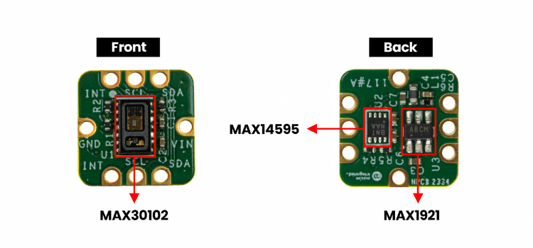
You can refer to the part marking image above for a clearer understanding.
This minimal approach also makes the overall block diagram simpler.
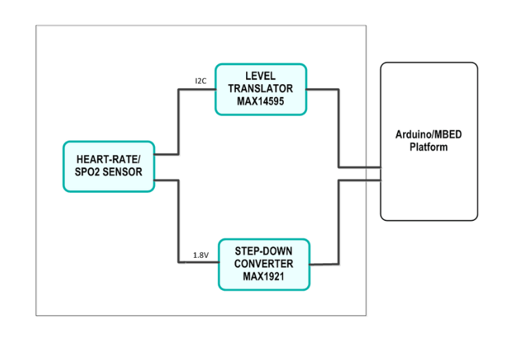
Three main ICs handle all the core operations.
Main Components Explained
| Component | Model | Function |
| Heart Rate/SpO2 Sensor | MAX30102 | Optical sensing with integrated red/IR LEDs and photodetector |
| Level Translator | MAX14595 | Voltage level shifting for 3.3V/5V I2C compatibility |
| Step-Down Converter | MAX1921 | Efficient power regulation from 2V-5.5V input |
You might already be familiar with the MAX30102, as it’s a more popular option for heart-rate/SpO2 sensing that comes as an all-in-one package. The other two ICs have dedicated jobs to do, making this module more versatile.
Understanding the MAXREFDES117 Module Pinout
The MAXREFDES117 module pinout features an unconventional four-sided design optimised for compact wearable integration. The pinouts are a little unusual compared to regular modules, but they really come in handy for real-time projects. Surprisingly, this module has pinouts on all four sides, two sides for I2C and the other two for power. Refer to the image below for a better understanding.
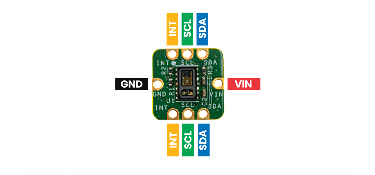
| Pin Name | Function | Side Location |
| VIN | Power Input (2V-5.5V) | Side 1 & 3 |
| GND | Ground Connection | Side 1 & 3 |
| SCL | I2C Clock Line | Side 2 & 4 |
| SDA | I2C Data Line | Side 2 & 4 |
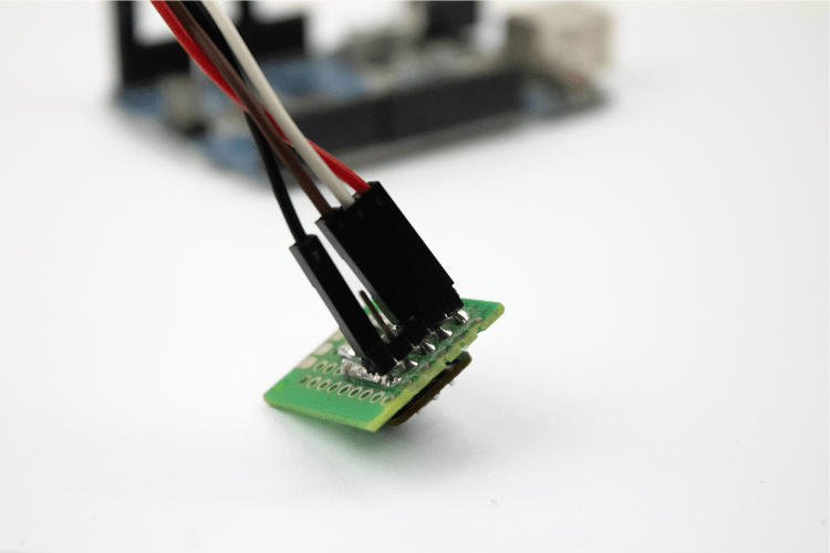
Looking at the pinouts, you can easily see that this is not a breadboard-friendly design. The MAXREFDES117 module pinout features an unconventional four-sided design optimised for compact wearable integration. That’s one of the downsides for regular breadboard users, but it can be solved with the help of simple jumper wires, as shown in the image below.
Available Resources and Documentation
The MAXREFDES117 module pinout is not breadboard-friendly by default due to its four-sided pin layout. By referring to the official resource site, you can get the module’s complete guide for both hardware and software aspects.
By downloading the 19.03 MB design files, you will receive:
- Bill of Materials (BOM)
- PCB CAD (Cadence)
- PCB Fab Package
- PCB Layout
- Schematic
- Arduino Files
- Mbed Files
With these files, we can completely recreate this module with minimal effort. For software development, there is dedicated Arduino support along with support for other mbed cores as well.
Interfacing the MAXREFDES117 with Arduino
Connecting the MAXREFDES117 optical heart rate module to Arduino is straightforward due to the integrated voltage regulation and level-shifting capabilities. This section provides the complete MAXREFDES117 Arduino interfacing guide.
Complete Wiring Configuration
| MAXREFDES117 Pin | Arduino UNO Pin | Function |
| VIN | 5V | Power Supply |
| GND | GND | Ground Reference |
| SCL | A5 (SCL) | I2C Clock Line |
| SDA | A4 (SDA) | I2C Data Line |
Hardware
On the hardware side, the connections are very simple. But as I already mentioned, the module is not breadboard-friendly, so I’m using a perfboard to make it breadboard-compatible. That’s because I only use this module for interfacing tutorials. Otherwise, you can go with direct soldering.
The connections are straightforward. Let’s see them in detail:
Power:
Since there is an inbuilt step-down converter, this module supports various voltage levels from 2V to 5.5V without any issues. This makes it adaptable for both 3.3V and 5V power inputs.
The onboard MAX1921 step-down converter accepts input voltages from 2V to 5.5V, making the MAXREFDES117 sensor module compatible with both 3.3V and 5V systems without external voltage regulation. In this case, Arduino uses 5V, so we can directly connect the MAXREFDES117 to the 5V and GND of the Arduino Uno. The connection looks like this:
Sensor Module → Arduino UNO
VIN → 5V
GND → GND
I2C Connection:
We don’t need to worry about the voltage level of the signal pins because there is an in-built voltage level shifter IC (MAX14595). The connection looks like this:
Sensor Module → Arduino UNO
SCL → SCL [A5]
SDA → SDA [A4]
Now, let’s get into the actual hardware connections, where I use the perfboard to connect the sensor to the breadboard and then connect the Arduino to the breadboard as well.
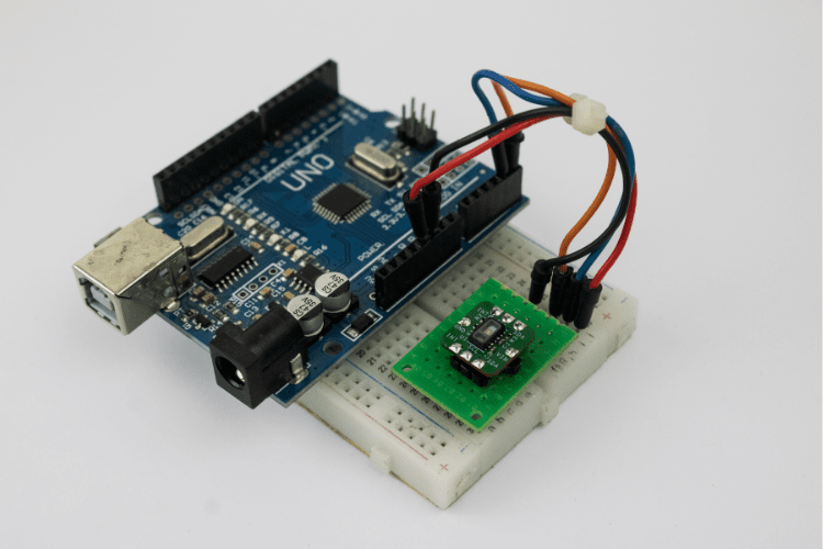
Above, you can see how I made the hardware connections.
MAXREFDES117 Arduino Programming Guide
Software
You have two approaches for programming the MAXREFDES117 Arduino project:
- Use the default software support provided by the manufacturer.
- Use any other library available for the MAX30102 from the Arduino Library Manager.
Whatever your choice, I decided to go with the second option.
Simply searching in the Library Manager, I found a library by SparkFun and decided to use it for quick testing.
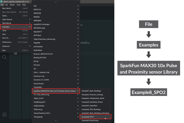
Opening up its built-in examples, I selected the one with the SpO2 reading feature and uploaded it to the Arduino. You can then see the live readings in the Serial Monitor while keeping your finger above the sensor on the module.
The MAXREFDES117 optical heart rate module represents the ideal balance of small footprint, ultra-low-power design and ease of integration for wearable health monitoring applications. The module supports a wide voltage range (2V-5.5V), comes with integrated level shifting, and includes comprehensive support with the Arduino® library. All of these features combine to allow anyone to easily prototype functioning systems for heart rate and SpO2 monitoring. The MAXREFDES117 sensor module can be used in a smartwatch, fitness tracker, or medical monitoring system while providing superior performance and versatility in any professional wearable design. The four-sided MAXREFDES117 module pinout design is not necessarily breadboard friendly, but, is designed and optimised for miniaturisation for real-world wearable implementation.
With this, we got to know more about the MAXREFDES117 sensor module. Hopefully, you got better insights into this module and will be able to make the best use of it.
Ready to get started? Don't forget to check out the attached video demonstration and explore the wealth of resources available to maximise your development experience with this sensor module.
Reference Sources
1. https://www.digikey.in/en/products/detail/analog-devices-inc-maxim-integrated/MAXREFDES117/6165562?s=N4IgTCBcDaILYEMAeAnApgMwCZoM4EZ8B2AYhAF0BfIA
2. https://www.analog.com/en/resources/reference-designs/maxrefdes117.html#rd-overview
3. https://www.analog.com/en/products/max1921.html
4. https://www.analog.com/en/products/max30102.html
https://www.analog.com/en/products/max14595.html
