 Anand D
Author

This is the teardown tutorial of ESP32-2424S012C, an ESP32 C3-based development board with an integrated display. This device comes in very handy, as it has our favourite ESP32-C3 onboard, a 1.28” IPS Capacitive Touch Screen display with a 240×240 px resolution. The coolest thing about this is that it can be custom-programmed to our specifications using a wide range of IDEs, including the Arduino IDE. There is a tutorial on our page that teaches you how to use this device with Arduino IDE and LVGL. Check the tutorial for an overview of its specifications, pin configurations, flashing Arduino code and more.
ESP32-2424S012C PCB Top Layer Analysis
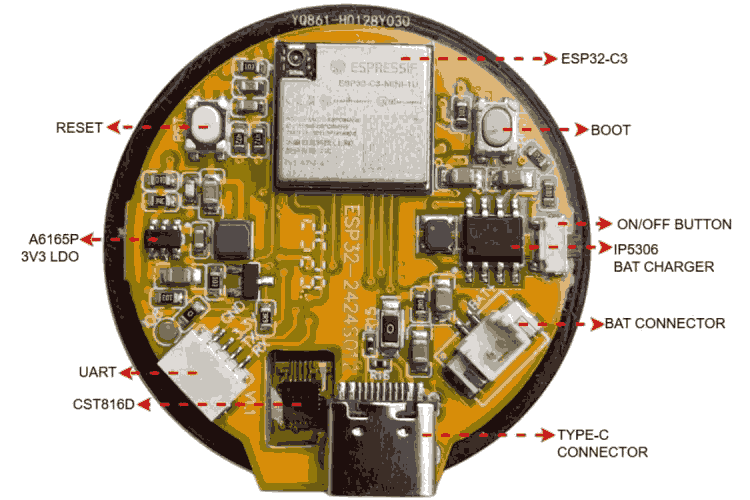
As you can see, the major parts of the PCB are highlighted in this diagram. The main part is the ESP32-C3 itself. We have 3 buttons: boot, reset and on/off. You can see the JST 1.25 mm 2-pin connector used to connect a 3.7V lithium battery to the board. IP5306 acts as the battery charger cum voltage booster for a 5V output. We have AO3402, an N-channel MOSFET that drives the backlight LED. To program the ESP, we have two options. One is by making use of the Type-C port, and the other way is via the JST-SH 1.00mm 4-pin connector provided for UART programming. A6165P is used as the 3V3 LDO regulator.
The display driver used is GC9A01, which comes as a COG(Chip-On-Glass). COG is a display packaging technology where the driver/controller IC is mounted/bonded directly onto the display glass rather than onto a separate PCB. This results in an extremely thin, lightweight, and compact display module that occupies less space while remaining fully functional as conventional ICs. The touch controller is CST816D, which comes as a COF(Chip on Flex), which means it's mounted onto the FPC cable.
ESP32-2424S012C PCB Bottom Layer
As we explore the bottom part of the PCB, we can see a 16-pin FPC that connects the display assembly to the main PCB. The metallic part that is seen on the backside of the backlight is provided to give strength to the whole assembly as well as to give some sort of heat dissipation for the backlight.
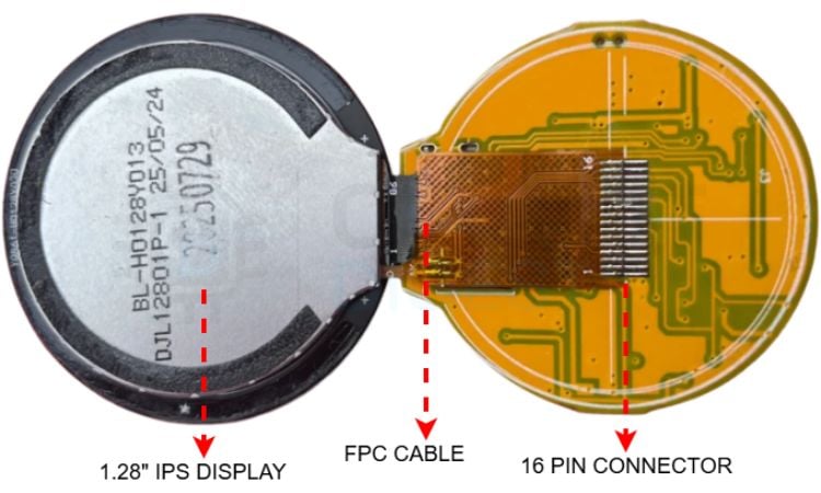
The COF-mounted touch driver is seen on the other part of this FPC cable, which can be seen in the PCB top layer diagram provided above.
ESP32-2424S012C Display Assembly Breakdown
Below is a diagram that shows the full display assembly of the ESP32-2424S012C development board.
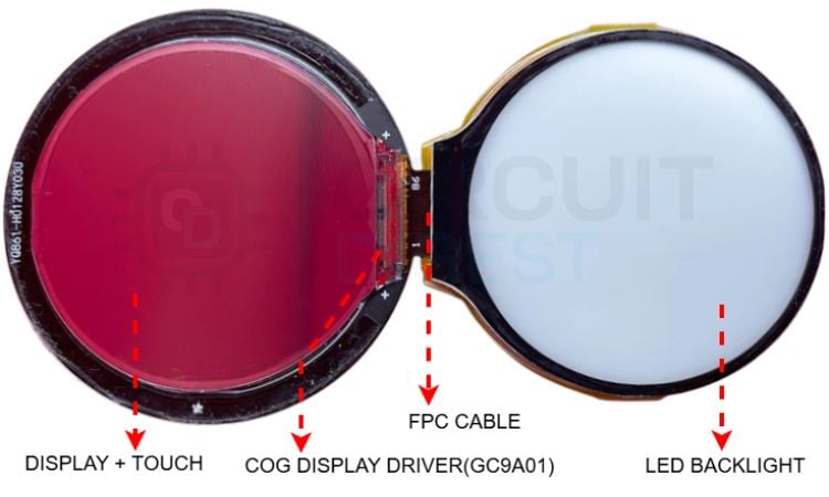
The COG display driver is clearly visible in the display glass substrate. It looks like a tiny black stripe on the glass substrate. If you look closer, you can also see tiny connections from the IC going to the FPC cable as well. The backlight that provides the required lighting for the assembly is also highlighted above. The display back is very shiny, like a mirror, so it captured these reddish reflections from the background.
ESP32-2424S012C Schematic - ESP32 C3 Circuit
This section covers the ESP32-2424S012C schematic in detail, tracing each functional block from the ESP32-C3 outward to the peripheral ICs.
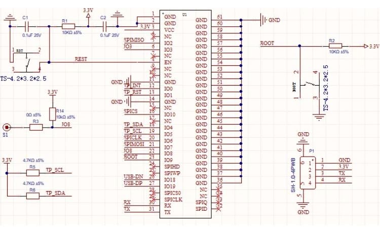
In this section, we’ll take a closer look at the ESP32-2424S012C schematic. This part of the schematic shows the main part of the PCB, the ESP32-C3 itself and its pins connected to other parts of the circuit. The boot button - it has a 10k pull-up and is connected to GPI09. In the PCB top layer, we can also see a pad labelled as S1, which is pulled up to 3V3 (refer to this schematic diagram) and connected to GPIO8. This pad is kept as an additional or backup boot button in case the standard boot button fails in any scenario.
We have the reset button that is connected to the ESP Enable pin. It has a pull-up of 10k. When the reset is pressed, it connects to GND and resets the ESP. We have 2 noise-filtering caps as well, labelled as C1 and C2. There is a dedicated UART port that is provided with this JST-SH 1mm 4-pin connector. We have the TX, RX, 3V3, and GND pins for programming. We can also see the pull-up resistors of the I2C pins.
ESP32-2424S012C FPC Pinout - Display and Touch Interface
The 16-pin FPC connector is the most information-dense part of this ESP32-2424S012C teardown pinout analysis
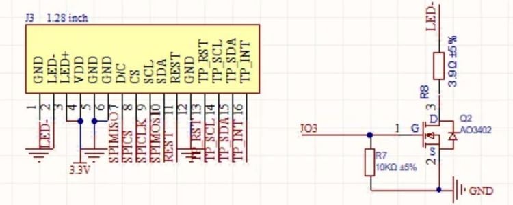
These are the FPC connector pins that connect the display-touch assembly to the main PCB. You can see that, starting from left, we have GND, the two LED pins for the backlight, VDD, GND, then the SPI pins for the display and then the I2C pins for the touch. The display uses SPI because we need to transfer a large amount of data very fast. The LED/backlight is switched on and off using this AO3402 N-channel MOSFET on the right side.
IP5306 Battery Charger and Boost Converter Circuit
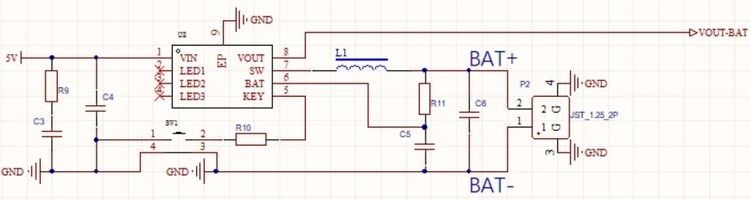
You can see that the battery connector goes to this IP5306 IC, which is a battery charger cum boost converter. It has an RC filter circuit at the input side to reduce noise. The application here is to charge the connected 3.7V lithium battery and boost the battery power to 5V DC, thanks to the high-frequency switching pulse generated at the SW pin. You can see that the switch on the side connects to the pin KEY, which is the push-button input of the IC. The datasheet says that short-pressing the button enables the output, and double-pressing disables the output that comes from pin 8. LED status pins are not used.
A6165P LDO Regulator - 5 V to 3.3 V Conversion
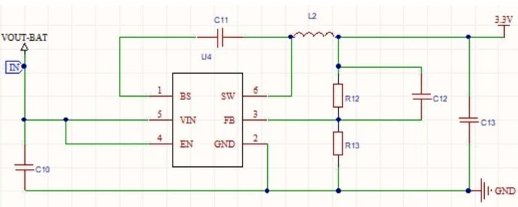
The VOUT-BAT or 5V out from the battery charger is fed into the LDO, which is A6165P. It generates stable 3V3 and feeds it right to our ESP board as well as the display-touch drivers.
Type-C Connector Circuit
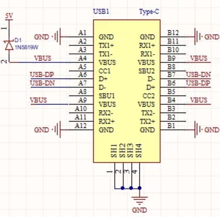
This is the Type-C connector circuit. You can see that it's connected to the D+ and D- pins of the ESP32, which are GPIO19 and 18. A Schottky diode is also provided at VOUT for reverse polarity protection.
Conclusion - What This Teardown Tells Us
The ESP32-2424S012C Development Board is a handy device that comes integrated with a good-quality IPS capacitive touch screen display, along with a huge number of online resources that can be used to develop any kind of project. It helps to get rid of messy wiring and make a very compact ESP32-based project that involves a display. These kinds of modules are being used to make virtual knobs, touch switches, smart watches and so on.
Overall, the hardware is of good quality and comes with the benefits of having an ESP32-C3 microcontroller inside. The hardware is so flexible that it can be customised with custom-designed cases or mounting attachments to meet any kind of specific requirements.
This development board opens up a great opportunity to learn and understand how the system works behind a smart display system or a smartwatch.

Excellent information. Load-bearing and corrosion-resistant earth pit covers can significantly enhance the reliability of electrical safety systems.