
The MAX32672FTHR is a compact development platform built around the MAX32672 for embedded evaluation and prototyping. It provides the key hardware resources needed for development, including onboard debugging, power management, user interface peripherals, and Feather-compatible expansion headers.
With many essential components already integrated onto the board, developers can move directly into firmware development and testing with minimal external setup. In this article, we’ll examine the hardware features of the board and the steps required to configure the development environment for programming it.
CircuitDigest presents the Learn, Build & Win by DigiKey! Submit your innovative embedded or electronics project idea for a chance to receive the MAX32672FTHR Evaluation Kit from Analog Devices and bring your project to life.
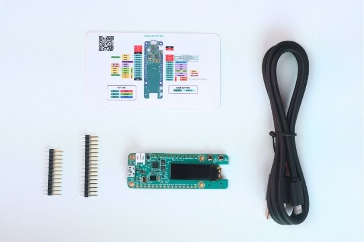
What’s inside the Box…?
The package includes the MAX32672FTHR board itself along with a 16-pin and a 12-pin Feather connector for accessing GPIOs, power, and communication interfaces, making it easy to interface with external modules. A USB-A to Micro-B cable is also provided, which is used for powering the board, programming it, and enabling serial communication, allowing you to get started with development and testing right away.
MAX32672FTHR Dev Board Features
The MAX32672FTHR is a compact development platform built around the MAX32672, offering a well-rounded set of processing capabilities, memory resources, and integrated peripherals for embedded system development.
MAX32672 Microcontroller
- ARM Cortex-M4 Processor with FPU up to 100MHz
- 1MB Dual-Bank Flash with Error Correction
- 200KB SRAM (160KB with ECC Enabled)
- 16KB Unified Cache with ECC
- Resource Protection Unit (RPU)
- Memory Protection Unit (MPU)
Integrated Peripherals
- MAX8819 PMIC with Integrated Charger
- On-Board DAPLink Debug and Programming Interface for Arm Cortex-M4
- Breadboard-Compatible Headers
- Micro USB Connector
- RGB Indicator LED
- User Pushbutton
- OLED Display
- SWD Debugger
- Virtual UART Console
Overall, the board includes a good mix of processing capability, onboard peripherals, and debugging support, making it suitable for learning, prototyping, and general embedded development.
MAX32672FTHR Dev Board Hardware Overview
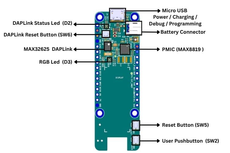
On the front side, the board primarily hosts the power management and interface circuitry. It has a Micro USB connector used for power, programming, and debugging, along with a battery connector for portable applications. The onboard PMIC handles power regulation and charging functionality. The integrated DAPLink interface (based on a secondary controller) enables drag and drop programming and debugging, supported by a dedicated status LED and control button. Additionally, user interaction components such as the reset button, user pushbutton, and a user-controllable RGB LED are placed here, making them easily accessible during testing and development.
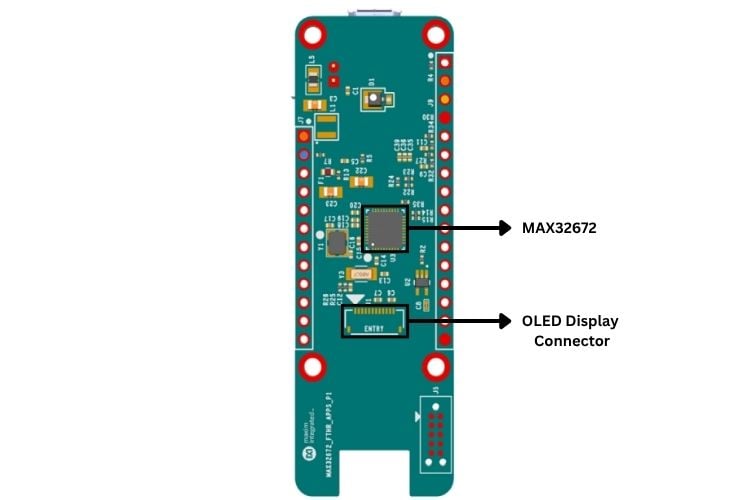
On the back side, the main processing unit, the MAX32672, is located along with its supporting components. This includes the essential circuitry required for stable operation, such as clocking and passive components. The OLED display connector is also positioned on this side, interfacing through the I2C bus.
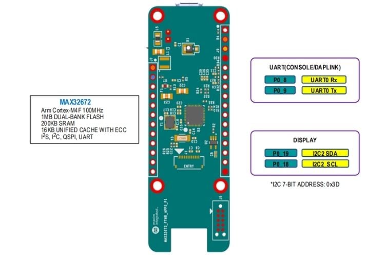
MAX32672FTHR Dev Pinout
The MAX32672FTHR provides a well-organised pinout layout that exposes most of the capabilities of the MAX32672. The board is designed to give easy access to power rails, communication interfaces, and general-purpose I/O, making it straightforward to interface with external peripherals and modules. Additionally, its breadboard-friendly form factor allows for quick prototyping and testing.
The pinout includes clearly defined power pins such as VBUS (USB input), BAT (battery input), 3V3, and GND for flexible power options. The GPIO pins are distributed across both sides of the MAX32672FTHR and are labelled with their corresponding port numbers (P0_x), making it easier to map them in firmware. Communication interfaces are integrated within these pins, including UART for serial communication, I2C for sensor and display interfacing, and SPI for high-speed data transfer, with the onboard OLED display also connected via the I2C interface.
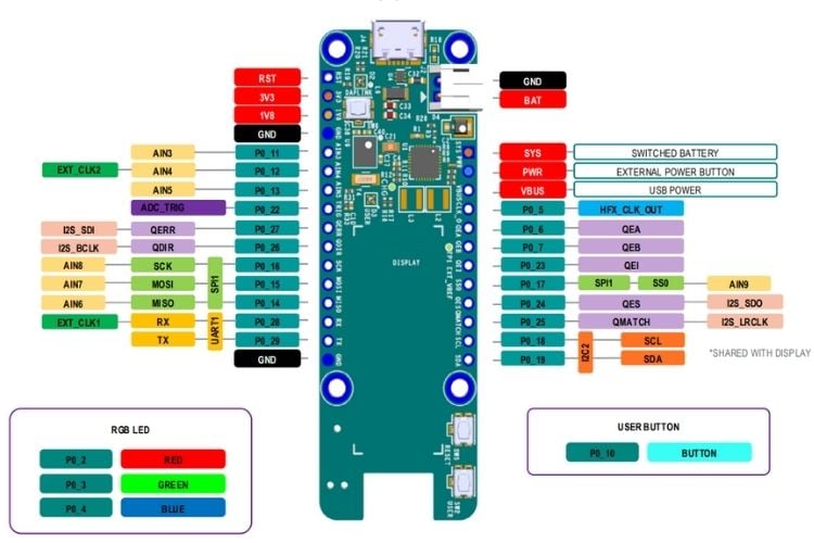
The board also includes multiple onboard user interface components mapped to specific GPIOs. It features three pushbuttons: SW2, a user-programmable button connected to Port 0.10; SW5, which provides a hardware reset through the RSTN pin of the MAX32672; and SW6, used for placing the onboard DAPLink adapter into maintenance mode for firmware updates. In terms of visual indicators, the board includes two RGB LEDs: D2, which is controlled by the DAPLink interface and not available for user applications, and D3, a user-controllable RGB LED connected to GPIO ports (P0.2 for Red, P0.3 for Green, and P0.4 for Blue), allowing flexible status indication through firmware.
So, these are the pinouts of the MAX32672FTHR, and it’s useful to see how onboard input devices like pushbuttons and output components such as the RGB LEDs and OLED display are directly mapped to the MAX32672 pins, making it easier to use them in your applications.
Setting Up the Maxim SDK in VS Code
Step 1: Download the Maxim SDK
Begin by downloading the Maxim Software Development Kit (MSDK), which includes the board support packages, peripheral drivers, example projects, and build tools required for developing on the MAX32672FTHR. Visit the official release page at and download the latest installer for your operating system. For Windows, download the MaximMicrosSDK_win.exe
%20-%20Vishnu%20S.jpg)
Once downloaded, install the SDK to a convenient location on your system, as this path will be used later during VS Code configuration.
Step 2: Install the Maxim SDK
After downloading the installer, install the Maxim SDK on your system. On Windows, right-click the downloaded installer and select “Run as Administrator”, then proceed through the setup wizard by clicking Next. Choose the installation directory (the default path, C:\MaximSDK, is typically recommended), and ensure that the required components are selected during installation, including Core MSDK, GCC Toolchain, OpenOCD, GNU Make, VS Code Support, etc.
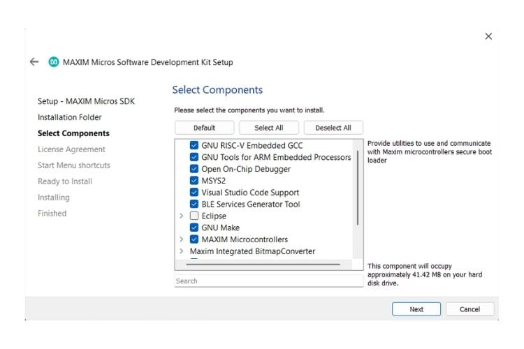
Once configured, click Install and wait for the setup process to complete. This will install the complete development environment needed for building and debugging projects for the MAX32672FTHR Board.
Step 3: Install and Configure Visual Studio Code
Download Visual Studio Code and install it on your system using the standard installation process for your operating system. Once installed, open VS Code and navigate to the Extensions panel from the left sidebar. Search for “C/C++”, select the extension published by Microsoft, and click Install. This extension provides IntelliSense, code navigation, and debugging support required for C/C++ embedded development with the Maxim SDK.
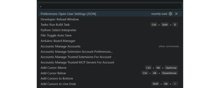
Step 4: Configure VS Code for the Maxim SDK
After installing the required tools, configure Visual Studio Code to recognize the Maxim SDK path. We can open the Command Palette using Ctrl + Shift + P, search for “Preferences: Open User Settings (JSON)”, and open the settings file.
Add the MAXIM_PATH entry pointing to your SDK installation directory (for example, C:/MaximSDK on Windows or ~/MaximSDK on Linux/macOS).
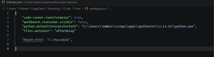
Save the file, then reopen the Command Palette and run Reload Window to restart VS Code and apply the new configuration. Once reloaded, VS Code will be able to detect the Maxim SDK for building and debugging MSDK-based projects.
Step 5: Open and Configure Your First Example Project
With the development environment ready, the next step is to open an example project from the Maxim SDK. Navigate to your Maxim SDK installation folder and locate the OLED_Demo example (under Examples/MAX32672/OLED_Demo). Copy this example folder to a working location such as your Desktop or Documents folder. Once copied, open Visual Studio Code, select File → Open Folder, and open the copied OLED_Demo project folder.
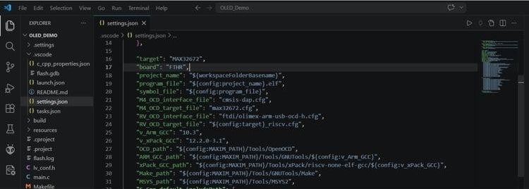
After opening the project, locate the file .vscode/settings.json inside the project directory. This file contains the board and target configuration used by the Maxim build system. Please update the "board" field to match your hardware configuration and Set it to "FTHR". Save the file, then reload VS Code using Ctrl + Shift + P → Reload Window so the updated board configuration is applied. The example project is now configured and ready for building and flashing.
Step 6: Build and Flash the Example Project
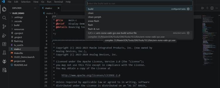
This is the final step, where the example project is compiled and flashed onto the board. In Visual Studio Code, press Ctrl + Shift + B and select the Build task to compile the project.
Once the build completes successfully, connect the Board to your computer using a USB cable, and the onboard DAPLink debugger should be detected automatically. Then press Ctrl + Shift + B again, choose the Flash task, and wait for the programming process to finish. During flashing, the DAPLink status LED will blink to indicate that the program has started flashing to the board. After flashing is complete, the firmware will start running on the board.
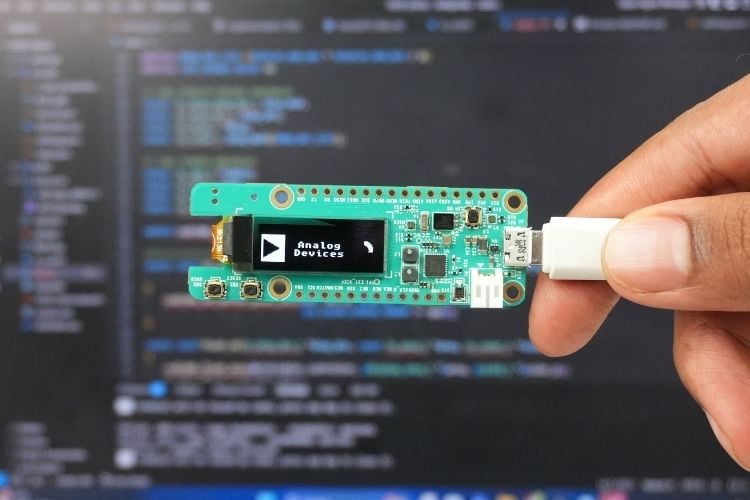
Output: After flashing the OLED demo firmware onto the MAX32672FTHR, the onboard OLED display initialises and displays the Analog Devices logo using the LVGL graphics library. This confirms that the firmware, display interface, and onboard peripherals are functioning correctly. The example demonstrates how graphical content can be rendered on the OLED using LVGL, which is integrated within the Maxim SDK example project.
Using Antigravity Editor and AI Agent for MAX32672FTHR Development
You can also use Antigravity Editor instead of VS Code to develop your MAX32672FTHR projects. The setup steps are exactly the same; you don't need to install MSDK again. Just open Antigravity Editor, update the MSDK location in the settings.json file (MAXIM_PATH), set your board to "FTHR", copy an example project, and build it the same way you did with VS Code. The build and flash process works identically in both editors, so you can easily switch between them whenever you want.
With AI assistance, you can quickly create diverse projects by modifying the example code provided for the MAX32672FTHR board. The MSDK includes pre-built examples for :
- GPIO control
- UART communication
- I2C sensors
- ADC readings
- PWM motor control
- OLED display graphics and
- low-power modes.
An AI agent can help you understand each example, explain how the code works, and guide you in combining multiple examples to build complex applications. For instance, you could mix the GPIO example with the display example to create a sensor monitoring dashboard, or combine ADC with I2C to build a multi-sensor data logger.
