
By Shekhar Nandanwar
The rapid advancement of Internet of Things (IoT) technology has made smart home and smart environment monitoring systems increasingly accessible and affordable. Embedded systems powered by low-cost, high-performance microcontrollers such as the ESP32 series now allow developers to create feature-rich, user-friendly interfaces with graphical displays, touch input, real-time sensing, and audio feedback — all within compact and power-efficient designs.
This project presents the design and implementation of a Smart Room Display and Monitoring System based on the ESP32-S3 microcontroller. The system combines:
A modern graphical user interface (GUI) built with LVGL (Light and Versatile Graphics Library)
Real-time display of time, date, room temperature and humidity
Wi-Fi connection status indication
Touch-based interaction
Visual alert/notification system
The main objectives of the project are:
To create an attractive, responsive, and intuitive user interface suitable for smart home or environment monitoring applications
To integrate multiple sensors and peripherals (display, touch, temperature/humidity sensor, audio codec) using clean and modular code
To demonstrate proper usage of the ESP-IDF framework, BSP (Board Support Package) abstraction layer, and LVGL on modern ESP32-S3 hardware
To handle real-world challenges such as API changes in LVGL, correct I2S audio configuration, and clean separation between UI logic and application behavior
The system is developed using ESP-IDF (Espressif IoT Development Framework) and targets typical ESP32-S3 development boards equipped with TFT displays (such as ILI9341, ST7789, or similar), capacitive touch, I2S audio output (e.g. MAX98357A / PCM5102 / ES8388), and a temperature-humidity sensor AHT20
Components Required
Component Name | Quantity | Datasheet/Link |
| ESP32 S3 BOX 3 | 1 | View Datasheet |
Circuit Diagram
This project was developed and demonstrated using the Espressif ESP32-S3-BOX development kit (ESP-BOX).
The ESP-BOX is a ready-to-use, integrated development platform that contains:
ESP32-S3 microcontroller
2.4-inch capacitive touch display (320×240)
Built-in speaker (via I²S audio codec)
Dual digital microphones
USB Type-C power interface
All major peripherals (display, touch controller, audio codec, etc.) are already soldered and internally connected on the board according to Espressif’s official design.
No custom circuit diagram is provided because:
No additional external components or wiring were added
No custom PCB was designed
All hardware connections follow the standard layout of the ESP-BOX development kit
Peripheral initialization and pin configuration are handled automatically by calling bsp_board_init() from the official esp-bsp component.
Hardware Assembly
Hardware assembly was kept minimal due to the use of the fully integrated Espressif ESP32-S3-BOX development kit.
The ESP-BOX already includes:
ESP32-S3 microcontroller
2.4-inch capacitive touch TFT display (320×240)
Built-in speaker (connected via I²S)
USB Type-C connector for power and programming
No additional sensors, displays, audio modules, or breakout boards were connected.
The only hardware modification / addition was:
One 18650 Li-ion battery cell (3.7V nominal) connected to provide portable / standalone power.
Assembly steps performed:
The original USB Type-C cable that came with the ESP-BOX (or a good quality USB-C cable) was used for initial programming and debugging.
For portable operation (demonstration without constant USB connection):
A single 18650 3.7V battery cell was connected to the board’s power input.
Connection was made to the 5V / VBUS line (most commonly via the USB-C connector breakout pads or using a simple battery holder + protection circuit + boost converter to 5V if required).
Important note: The ESP-BOX is designed to be powered via USB-C at 5V. Direct connection of a 3.7V battery without proper voltage conversion is not recommended for long-term use.
Code Explanation
This is the main application code for your Smart Wellness Clock project running on ESP32-S3-BOX
What the complete program does:
Initializes the display and shows the LVGL-based user interface (clock, date, room temp/humidity, Wi-Fi status, alert popup)
Connects to Wi-Fi (using your home network credentials)
Synchronizes time from the internet using NTP (so the clock shows real time)
Reads temperature and humidity from an AHT30 sensor every 2 seconds
Updates the UI every second with current time/date
Updates the room temperature & humidity display when new sensor values are available
Shows correct Wi-Fi connected/disconnected status on the screen
Code Structure:
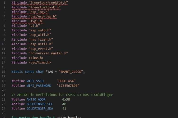
We are using FreeRTOS (tasks, delays)
ESP-BSP for easy board initialization (display, backlight, etc.)
LVGL + your custom ui.h for the graphical interface
Wi-Fi, SNTP (time sync), NVS, event loop, I²C driver
Hardcoded Wi-Fi credentials (common in development, later better to use menuconfig or provisioning)
I²C pins GPIO40 (SCL) and GPIO41 (SDA) — this is specific to some ESP32-S3-BOX variants with goldfinger expansion
2. AHT30 Sensor Functions
init_aht30_bus()
Configure I²C bus (port 0, SCL/SDA pins)
Enable internal pull-ups
Create I²C master bus
Attach AHT30 device to the bus
This sets up hardware communication between ESP32 and AHT30.
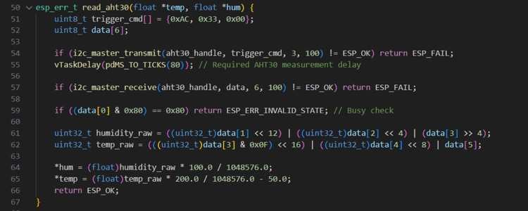
3.Reading Temperature & Humidity from AHT30
Send trigger measurement command
Wait 80 ms (AHT30 needs conversion time)
Read 6 bytes of sensor data
Convert raw data into:
Humidity (%)
Temperature (°C)
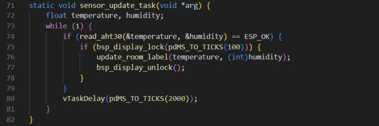
4.Sensor Update Task (FreeRTOS)
Runs every 2 seconds
Reads temperature & humidity
Updates LVGL UI safely
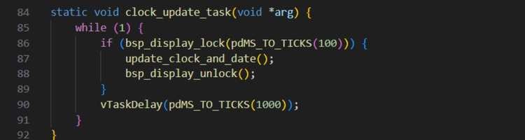
5.Clock Update Task (FreeRTOS)
Updates time & date every second
Uses NTP-synced system time
6.Wi-Fi Event Handler
Handles Wi-Fi lifecycle events:
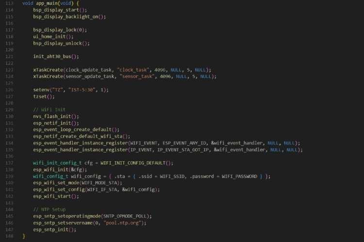
7.Main Application Entry – app_main()
In the app_main() function, the application starts by initializing and powering up the display using the ESP-BOX-3 board support package. The display driver is started, the backlight is turned on, and the home UI screen is initialized using LVGL. The display is locked during UI initialization to ensure thread-safe access because multiple FreeRTOS tasks will later update the screen. Once the UI is ready, the AHT30 temperature and humidity sensor is initialized by configuring the I²C bus on the ESP32-S3-BOX-3 goldfinger pins, allowing the system to start reading environmental data.
After the hardware setup, two FreeRTOS tasks are created: one task updates the clock and date every second, and the other reads the temperature and humidity sensor every two seconds. These tasks run in parallel, ensuring that time and sensor data are refreshed continuously without blocking each other. The system time zone is then set to Indian Standard Time (IST), so when the time is synchronized from the internet, it is automatically converted from UTC to local time.
Next, the Wi-Fi subsystem is initialized. Non-volatile storage (NVS) is set up, the network interface and event loop are created, and Wi-Fi event handlers are registered to monitor connection status. The ESP32 is configured in station mode using the provided SSID and password and then started. Finally, the SNTP (Network Time Protocol) service is initialized with a public NTP server. Once Wi-Fi is connected, the device automatically synchronizes the system clock with the internet, enabling the smart clock to display accurate real-time information on the screen.
GitHub Repository


