

Home Automation has always been inspiring projects for most of us. Toggling an AC load from the comfort of our chairs or bed of any room without reaching for the switch in another room sounds cool doesn’t it!!, Thanks to the ESP8266 modules this idea can be easily implemented with subtle knowledge on electronics.
In this project let us learn how to make a Junction Box whose switches can be toggled remotely using your Phone or Computer with active internet connection. This project is capable of toggling any two AC loads whose current rating is not more than 5A or ~800Watts. Once you understand the concept you can extend the number or AC loads by using advanced ESP modules and also increase the power rating of the loads by using high rating relays.
This tutorial assumes you have experience is using ESP8266 modules with Arduino IDE. If not visit Getting Started with ESP8266 WiFi Transceiver (Part 1) and Getting Started with ESP8266 (Part 3): Programming ESP8266 with Arduino IDE and Flashing its Memory tutorials before proceeding.
Hardware Required:
The hardware required for this project is listed below:
- ESP8266
- FTDI module (for Programming)
- 3V 5A Electromagnetic Relay (2Nos)
- AC-DC converter module (5V/700mA or above)
- BC547 (2Nos)
- LM317 Regulator
- 220ohm and 360ohm Resistor
- 0.1 and 10uf capacitor
- IN007 diode (2Nos)
- Junction box
- Wires for connection
Schematic Explanation:
The complete Schematic of this project is shown below:

The Schematics consists of an AC to DC converter module whose output will be 5V and 700mA. Since our ESP8266 modules work on 3.3V we have to convert the 5V to 3.3V. Hence, a LM317 Variable voltage regulator IC is used to regulate 3.3V for the ESP modules. In order to toggle the AC loads we have used an electromagnetic relay, this relay requires 3V to energize and can withstand up to 5A flowing through the Common (C) and the normally open (NO) pin of the Relay. In order to drive the relays we have used a BC547 NPN transistor which is switched by the GPIO pins of the ESP modules.
Since the ESP8266 Modules comes with inbuilt GPIO pins the project has come down to be fairly simple. But care should be taken while using the GPIO pins of a ESP module, they are discussed below.
TIPS TO USE ESP8266 GPIO PINS:
- The ESP8266-01 module has two GPIO pins which are the GPIO0 and GPIO2 pins respectively.
- The maximum source current of the GPIO pins are 12mA.
- The maximum sink current of the GPIO pins are 20mA.
- Due this low current we cannot drive any decent loads like a relay directly from the pins, a driver circuit is mandatory.
- There should not be any load connected to the GPIO pins when the ESP module is powered on. Else module will be stuck into a reset loop.
- Sinking more current than the recommended current will fry your ESP8266 module’s GPIO pins so be cautious.
To overcome the above shortcomings of the ESP8266 module we have used a BC547 to drive the Relays and used a switch between the Emitter and ground of the BC547 Transistors. This connection has to be open when the ESP module is powered ON, then is can be closed and left as such.
Hardware:
Once you understand the schematics simply solder the circuit on a piece of Perf Board. But make sure that your board will fit into the Junction box also.
AC-DC converter (5V/700mA):
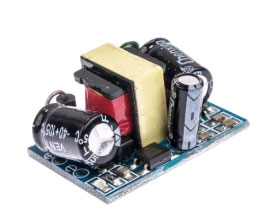
The AC-DC converter used in this project outputs 5V with 700mA continuous and 800mA peak current. You can easily buy one similar online since they are easily available. Designing our own converter or using a battery will be less efficient for our Project. Once you buy this module simply solder a wire to the input terminal and you should be ready to go with the rest of the circuit.
Once everything is soldered it should look something like this.
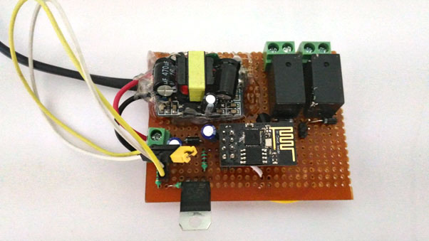
As you can notice I have used three 2-pin terminal boxes. Out of which one is used to feed in the +V from the AC-DC converter module and the other two is used to connect the AC loads to the Relay.
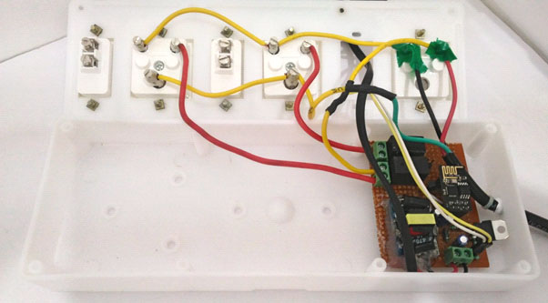
Now let us connect the Terminals on the Junction box to our Perf board.

You can notice that my junction box has three terminals (plug points). Out of which one (the right most) is used to power our AC-Dc converter module the other two is used to connect the AC loads. As you can see the Neutral wire (black wire) is connected to all three plug points. But the Phase wire is (yellow wire) is left free. The phase ends of the two plug points (two red wires) are also left free. All these three free wires should be connected to the Relay terminals that we added to our Perf board as shown below
My Perf board fits perfectly into the junction Box, make sure yours does too. Once the connections are made upload the program to the ESP module mount it on the Perf board and screw the Junction box.
ESP8266 Program:
Our ESP8266 Module is programmed using the Arduino IDE. As said earlier if you want to know how to program your ESP using Arduino IDE visit the tutorial in the link. The complete program is given at the end of this tutorial. The concept of the program is self explanatory however few important lines are discussed below.
const char* ssid = "BPAS home";  //Enter you Wifi SSID here

const char* password = "cracksun"; //Enter your password here
The ESP module will act as Station and Access point in our project. So it has to connect to our Router when acting as station. The above lines of code are used to feed in the SSID and password of our Router. Change it according to your router.
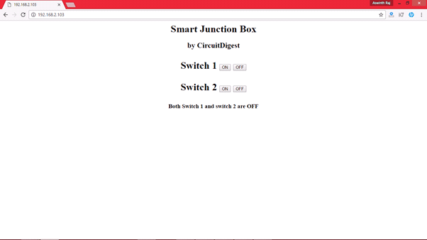
mainPage += "<h1 align=\"center\">Smart Junction Box</h1><h2 align=\"center\">by CircuitDigest</h2><h1 align=\"center\"><p>Switch 1 <a href=\"switch1On\"><button>ON</button></a> <a href=\"switch1Off\"><button>OFF</button> </a></p>"; mainPage += "<p>Switch 2 <a href=\"switch2On\"><button>ON</button></a> <a href=\"switch2Off\"><button>OFF</button> </a></p>"; feedback = "<h3 align=\"center\">Both Switch 1 and switch 2 are OFF</h3>";
When we connect to the IP address of the module, a webpage will be displayed which runs on HTML. This HTML code has to be defined in side our Arduino Program as shown above. This does not required you to know HTML before hand, just read the HTML tags and compare them with the output you will understand what each tag represents.
You can also copy this HTML code and paste it in a txt file and run it as a HTML file for debugging purpose.
while (WiFi.status() != WL_CONNECTED) {

    delay(500);

    Serial.print(".");

  }

  Serial.println("");

  Serial.print("Connected to ");

  Serial.println(ssid);

  Serial.print("IP address: ");

  Serial.println(WiFi.localIP());
We are also using the Serial monitor option for debugging the ESP module and know what status the program is currently operating. The serial monitor will output “.” Until the ESP has established a connection with the Router. Once the connection is established it will give you the IP address of the web server, the code for the same is shown above.
  server.on("/switch1On", [](){

    feedback = "<h3 align=\"center\">Switch 1 turned ON</h3>";

    currentPage=mainPage+feedback;

    server.send(200, "text/html", currentPage);

    currentPage="";

    digitalWrite(GPIO_0, HIGH);

    delay(1000);

  });
Once we know the IP address we can access the HTML code using that IP on our browser. Now when each button is pressed a request will be sent to ESP module as a client. Based on this client request the module will respond. For example if the client has requested for “/switchOn” the module will update the HTML code and send it to the client and also turn GPIO pin HIGH. The code for the same is shown above. Similarly for each action a server.on() is defined.
Output:
Once you are ready with the Hardware and the Program, upload the program to our ESP8266 module as shown in this tutorial. Then click on serial monitor of the Arduino IDE you should see something like this if the SSID and password match
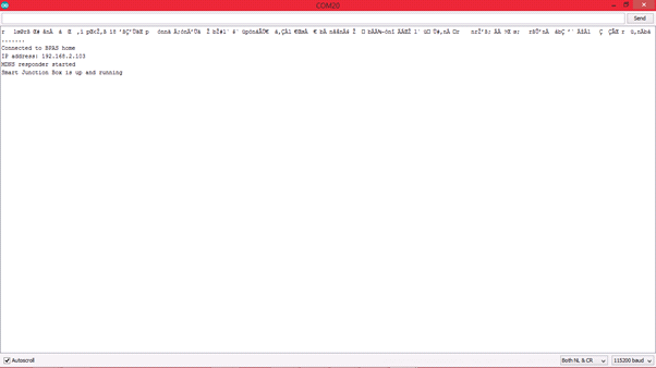
Make a note of the IP address that is displayed in the Serial monitor. In my case the IP address is ”http://192.168.2.103” We have to use this IP in our browser to access the ESP webpage.
Now, place the ESP module in our Relay board close the junction box and power it ON, then short the GPIO pins to the load. If everything has worked properly when you enter the IP address in your Browser you should see the following screen
Now simply turn ON/OFF the switch you like to and it should be reflected on the actual Hardware. That is it guys not you can Toggle your favorite AC load by simply connecting them to the plug point. Hope you liked the project and got it working, if not use the comment section I will be happy to help you.
The complete working of this DIY smart junction box project is shown in the Video below.
Complete Project Code
/*Program for : Smart Junction box for Home Automation
* Program by :Aswinth Raj
* Published on : circuitdigest.com
* Dated:11-05-2017
*/
#include <ESP8266WiFi.h>
#include <WiFiClient.h>
#include <ESP8266WebServer.h>
#include <ESP8266mDNS.h>
MDNSResponder mdns;
const char* ssid = "BPAS home"; //Enter you Wifi SSID here
const char* password = "cracksun"; //Enter your password here
ESP8266WebServer server(80);
String mainPage = ""; //The default page
String feedback = ""; //Gives staus of the switch
String currentPage = ""; //Combines main and feedback page
int GPIO_0 = 0; //Pin defanition
int GPIO_2 = 2; //Pin defanition
void setup(void){
mainPage += "<h1 align=\"center\">Smart Junction Box</h1><h2 align=\"center\">by CircuitDigest</h2><h1 align=\"center\"><p>Switch 1 <a href=\"switch1On\"><button>ON</button></a> <a href=\"switch1Off\"><button>OFF</button> </a></p>";
mainPage += "<p>Switch 2 <a href=\"switch2On\"><button>ON</button></a> <a href=\"switch2Off\"><button>OFF</button> </a></p>";
feedback = "<h3 align=\"center\">Both Switch 1 and switch 2 are OFF</h3>";
currentPage = mainPage+feedback;
// preparing GPIOs
pinMode(GPIO_0, OUTPUT);
digitalWrite(GPIO_0, LOW);
pinMode(GPIO_2, OUTPUT);
digitalWrite(GPIO_2, LOW);
delay(1000);
Serial.begin(115200);
WiFi.begin(ssid, password);
Serial.println("");
// Wait for connection
while (WiFi.status() != WL_CONNECTED) {
delay(500);
Serial.print(".");
}
Serial.println("");
Serial.print("Connected to ");
Serial.println(ssid);
Serial.print("IP address: ");
Serial.println(WiFi.localIP());
if (mdns.begin("esp8266", WiFi.localIP())) {
Serial.println("MDNS responder started");
}
server.on("/", [](){
currentPage = mainPage+feedback;
server.send(200, "text/html", currentPage);
currentPage = "";
});
server.on("/switch1On", [](){
feedback = "<h3 align=\"center\">Switch 1 turned ON</h3>";
currentPage=mainPage+feedback;
server.send(200, "text/html", currentPage);
currentPage="";
digitalWrite(GPIO_0, HIGH);
delay(1000);
});
server.on("/switch1Off", [](){
feedback = "<h3 align=\"center\">Switch 1 turned OFF</h3>";
currentPage=mainPage+feedback;
server.send(200, "text/html", currentPage);
currentPage="";
digitalWrite(GPIO_0, LOW);
delay(1000);
});
server.on("/switch2On", [](){
feedback = "<h3 align=\"center\">Switch 2 turned ON</h3>";
currentPage=mainPage+feedback;
server.send(200, "text/html", currentPage);
currentPage="";
digitalWrite(GPIO_2, HIGH);
delay(1000);
});
server.on("/switch2Off", [](){
feedback = "<h3 align=\"center\">Switch 2 turned OFF</h3>";
currentPage=mainPage+feedback;
server.send(200, "text/html", currentPage);
currentPage="";
digitalWrite(GPIO_2, LOW);
delay(1000);
});
server.begin();
Serial.println("Smart Junction Box is up and running");
}
void loop(void){
server.handleClient();
}
Comments
The LM317K has its label swapped. The circuit and the pin numbers will remain the same. I will change the label and upload it soon.
Thanks again Tim Black.
Mistake? In "3.3 Volt supply" part on Schematic of this project is shown above:
the marking of "VI" and "VO" pin of LM317 is on the right place?
Hi csa,
Yes the labels have been swapped thanks for spotting it out. Will correct is ASAP and upload the right one
please i am new but interested in the project. i will be grateful if you can help me .i try the code but not responding.thanks
Hi Bob,
Sure, I will help you out. But provide me more info on your problem. What do your mean by "not responding" which step are you stuck with?
Have you tried a simple blink program and is it working?
Hello Raj.
Thanks Raj. Please I am ok now . I found out that I did not sign correct SSID and password.
Secondly how do I connect from everywhere?
My regards
Thanks Bob, glad you got it working.
If you want to access this website from anywhere, you have to enable "Port forwarding" on your Router. I will soon make a tutorial on how to do it. Stay tuned..
sir, I am intrested in this project. how can I use a voice control insted of wifi...
Hi Ameen,
This project can be upgraded for voice control. Read this link
To know how to use a voice control
hii very useful project i have some Q
if i want to using my smart phone wifi as like BT so how can i
my email is
Hi chetan,
Sorry, I could not understand your question!!
If you want to control these loads using E-mail. It is also possible. In that case you should read this link
Why do we need to 'short' the esp8266 using a jumper pin before turning on connected plugs. Can we have a permanent solution to that ?
During power up the jumper should be shorted to prevent it from getting into programming mode. There is solution for that would share the link once i find it
Hi Dear,
I make this Projects working very well. but i am changing some thing 1. how to fixed IP address of my module in my router (i.e power up my router after power failure IP address changed) . 2. ON OFF button of web page is very small how to large it. Plz solve my problem I am very thankful to you.
sir im not able to identify the i/p and o/p of the power module...can you please explain how to connect the terminals
Which power module are you using? It should have a silkscreen marking on it
when uploading d program to esp it is showing error ,pls hw can i go about it

It appears that you have the input and output swapped on the LM317k