
By Rishabh Jain
Modern smart home systems typically rely on cloud connectivity and internet access, which introduces latency, privacy concerns, and dependency on external infrastructure. In many real-world scenarios, reliable internet connectivity is not always available, and users still require fast, secure, and private home automation.
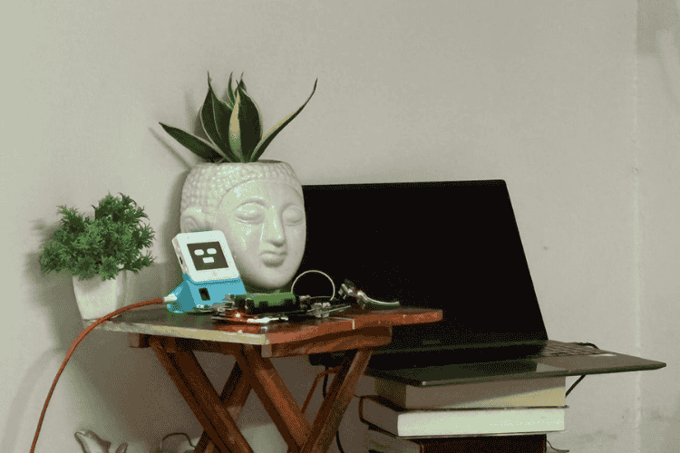
The Smart Home Automation and Monitoring Hub is a centralized smart home controller developed to manage and monitor multiple IoT devices from a single interface. This project presents a fully local, router-free smart home hub built using ESP32 devices. The entire system operates without internet connectivity, ensuring low latency, high reliability, and complete data privacy. The system is built using an ESP32-S3-BOX-3 platform and integrates voice wake-up, environmental sensing, and wireless communication using ESP-NOW and Wi-Fi/HTTPS. The device acts as the “brain” of the home, communicating with remote ESP nodes to collect indoor weather, appliance control & video surveillance while providing a touch-enabled graphical interface for real-time control and feedback.
The system supports voice-controlled appliance automation using the ESP
Speech Recognition (ESP-SR) stack. Users can control home appliancessuch as lights, air conditioners, TVs, and other IR-based devices using natural voice commands. Legacy appliances are supported through an onboard IR transmitter and learning mode, allowing the system to replace traditional remote controls.
This project was created to solve the problem of fragmented smart home devices that operate independently and require multiple apps or hubs. By combining automation, monitoring, and communication into one device, the hub provides a low-power, responsive, and scalable solution for smart homes.
Features
1. Smart Home Hub (ESP32-S3 BOX)
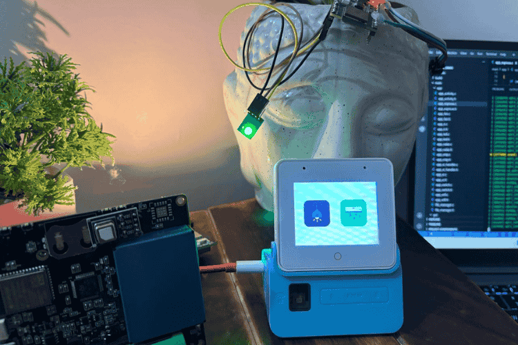
The ESP32-S3 Box acts as a central controller with a touchscreen dashboard.
It integrates multiple wireless nodes and provides a unified interface for monitoring, automation and multimedia.
Highlights
- Touchscreen dashboard using LVGL
- Speech recognition support
- IR transmitter & receiver for legacy appliances
- Wi-Fi + ESP-NOW hybrid communication
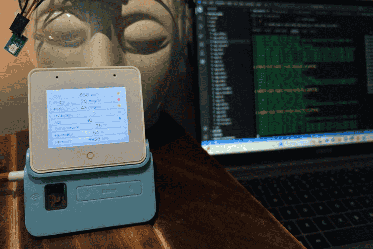
2. Indoor Weather Monitoring
A dedicated sensor node continuously measures indoor environmental conditions and sends real-time telemetry to the hub using ESP-NOW.
Measured Parameters
- CO₂ concentration
- Temperature & Humidity
- Air Pressure
- PM2.5 & PM10 particles
- UV Index
- Air Quality Index (AQI)
Key Benefits
- Real-time updates on dashboard
- Visual air-quality indicators
- Low-power wireless communication
3. Wireless Appliance Control
A relay node receives ESP-NOW commands from the hub to control electrical appliances.
Key Benefits
- Instant response (low latency ESP-NOW)
- Works without internet/router
- Reliable peer-to-peer communication
4. Voice + IR Control for Legacy Devices
The hub includes built-in microphone and IR transmitter to control devices that use traditional remote controls.
Supported Devices
- Television
- Air Conditioner
Key Benefits
- Voice-activated control
- IR learning mode for custom remotes
- Enables automation of non-smart appliances
5. Live Surveillance System
An ESP32-CAM node streams live video over HTTP, which is displayed directly on the dashboard.
Key Benefits
- Real-time monitoring
- No cloud required
- Local network streaming
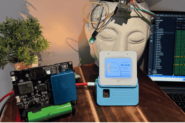
6. Energy Monitoring Dashboard
The system includes an energy usage interface showing live power consumption and estimated electricity costs.
Displayed Data
- Real-time power usage (Watts)
- Monthly energy consumption (kWh)
- Estimated monthly electricity bill
- Daily energy cost tracking
7. Hybrid Communication Architecture
The system combines two wireless technologies for efficiency:
ESP-NOW - Low-latency device-to-device control & telemetry
Wi-Fi HTTP - High-bandwidth video streaming
This hybrid approach ensures low power consumption, high reliability, and scalability.
8. Radar Based Device Wake-Up
A radar presence sensor integrated inside the ESP32-S3 Box detects when a user approaches the device.
The display automatically wakes and activates the dashboard, enabling a touchless user experience.
Components Required
- ESP32S3-BOX-3, Buy from Digikey
- ESP32-S3-CAM Module
- ESP32-C3 Dev Module
- ESP32-S3 Custom Sensor Hub
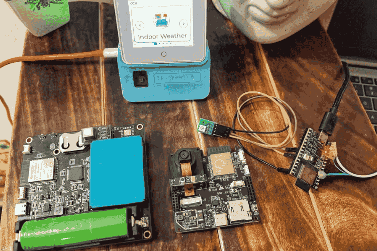
Note: For this project, a custom-designed environmental sensor node was developed using an ESP32-S3 + STM32 architecture.
This node integrates multiple air-quality and environmental sensors, including:
- PM7003 – Particulate Matter Sensor (PM1.0 / PM2.5 / PM10)
- SCD40 – CO₂ Sensor
- LTR390 – UV & Ambient Light Sensor
- BME688 – Temperature, Humidity, Pressure & Gas Sensor
The STM32 is used for sensor interfacing and data acquisition, while the ESP32-S3 handles wireless communication using ESP-NOW.
However, the system is designed to be hardware-flexible. Any ESP32-based board with compatible environmental sensors can be used to replicate the sensor node functionality.
For the surveillance module, this project uses a CamThink ESP32-S3 Camera module for live video streaming.
As an alternative, users may use the widely available standard ESP32-CAM module, which is fully compatible with the system architecture.
Project Objectives
During this project, the following integrations and features were implemented:
- Development of 5 touchscreen UI screens using LVGL
- Integration of ESP-NOW wireless communication
- Local HTTP video streaming & JPEG decoding
- Integration of Radar-based wake-up detection
- Modification of ESP-SR voice recognition & IR learning and transmission file.
Project Setup & Development
Environment
The project uses a hybrid developmentworkflow combining ESP-IDF and Arduino IDE, depending on the node functionality.
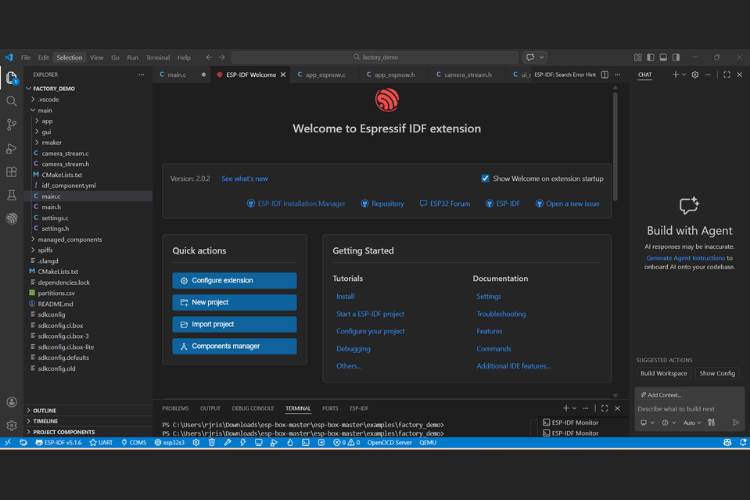
Master Hub (ESP32-S3 Box)
Developed using ESP-IDF inside Visual Studio Code.
Tools used
- Visual Studio Code
- ESP-IDF Extension for VS Code (V5.1.6)
- Python (latest version) – required by ESP-IDF toolchain
Follow these official steps to download and setup esp-idf.
The factory demo was used as the base firmware and extended to implement custom features and multi-node integration. You can download or clone this repository to get started with demo codes.
Circuit Diagram
Hardware Assembly
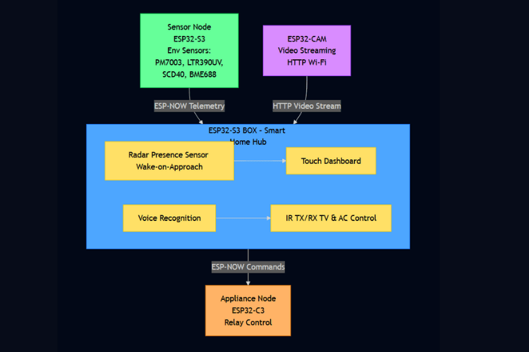
- Hardware Overview
This project primarily focuses on system integration and software architecture using ready-to-use development boards and custom PCBs. Since the modules are pre-designed and assembled, a detailed circuit schematic is not included.
Instead, the hardware architecture is presented as a module-level block diagram, showing how the different devices communicate and interact.
Code Explanation
UI Pages Implementation (LVGL)
The ESP32-S3 Box uses the LVGL graphics library to implement a multi-screen touchscreen dashboard.
Each feature (Weather, Devices, Camera, Energy, etc.) is implemented as an individual LVGL page.
To avoid repeating code, a base page template is created and reused by all screens.
1. Base Page Creation
lv_obj_t* create_base_page(void (*end_cb)(void), const void *img, const char *title) This function creates a full-screen container that acts as the root object for every screen.
Instead of writing page setup repeatedly, every screen calls this function first.
- Create full screen LVGL object
page = lv_obj_create(lv_scr_act()); lv_obj_set_size(page, LV_HOR_RES, LV_VER_RES); lv_obj_clear_flag(page, LV_OBJ_FLAG_SCROLLABLE); This creates a full display-sized container where all widgets of that screen will be placed.
So every screen starts with a clean canvas.
- Store page exit callback
g_active_page_end_cb = end_cb; Each page provides a callback that will run when the user exits the page.
This allows safe navigation back to the main menu.
- Capacitive Touch Button as BACK Button
The ESP32-S3 Box has a hardware capacitive touch button.
Instead of using an on-screen back button, this physical button is mapped as global BACK.
bsp_btn_register_callback( BSP_BUTTON_MAIN, BUTTON_PRESS_UP, global_cap_btn_back_cb, NULL );- Safe Page Closing
LVGL objects must be deleted inside the LVGL thread.
So we use an async callback:
lv_async_call(lvgl_page_close_async, NULL); - Deletes the page safely
lv_obj_del(page); ui_main_menu(0); This returns the user to the main launcher screen.
2. Indoor Weather Screen
void ui_weather_start(void (*end_cb)(void)) This screen displays live environmental data received via ESP-NOW.
- Create base page
lv_obj_t *page = create_base_page(end_cb, &indoor, "Indoor Weather"); Now we have a blank full-screen page ready.
- Apply background style
lv_obj_set_style_bg_color(page, lv_color_hex(0xECEFF1), 0); lv_obj_set_style_bg_grad_color(page, lv_color_hex(0xDADDE1), 0); This creates the soft gradient background.
- Create vertical list container
lv_obj_t *list = lv_obj_create(page); lv_obj_set_flex_flow(list, LV_FLEX_FLOW_COLUMN); The screen uses Flex Layout to stack items vertically.
- Creating Dashboard Rows
dashboard_row_t create_row(...) Each row contains:
- Sensor name
- Sensor value
- Unit
- Status dot
- Updating values from ESP-NOW data
lv_label_set_text_fmt(t_co2.value, "%d", g_latest_data.co2); Values are taken from:
sensor_packet_t g_latest_data; This struct is filled by the ESP-NOW receiver.
So the dashboard updates live sensor values.
Similarly, all other pages are designed.
Linking Pages to Main Menu (ui_main.c)
After creating individual LVGL pages, the next step is to connect them to the launcher screen.
This is done in ui_main.c, which acts as the navigation controller of the UI.
The flow is:
Boot Screen → Main Menu → Open Screen → Back → Main Menu- Declaring Screen Icons
All menu icons are stored as LVGL images:
LV_IMG_DECLARE(indoor) LV_IMG_DECLARE(remote_control) LV_IMG_DECLARE(doorbell) LV_IMG_DECLARE(electric_meter) LV_IMG_DECLARE(ir_remote)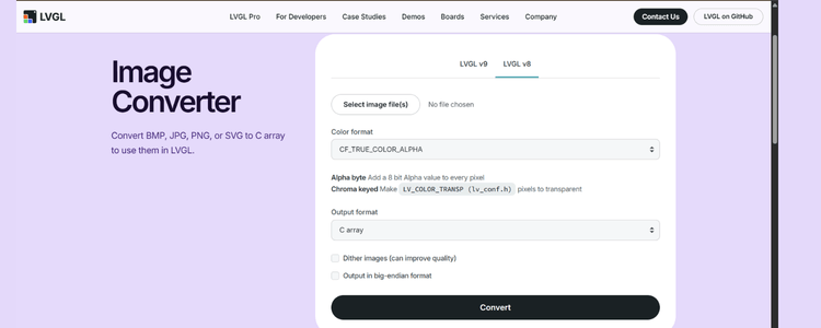
Icons were converted to C arrays using the LVGL Image Converter, and placed in:
gui/images/LVGL loads these images directly from firmware memory.
- Main Menu Item Table
static item_desc_t item[] = { { "Indoor Weather", &indoor, ui_weather_start, weather_end_cb },
{ "Device Control", &remote_control, ui_devices_start, devices_end_cb },
{ "Surveillance", &doorbell, ui_surveillance_start, surveillance_end_cb },
{ "Energy Usage", &electric_meter, ui_energy_start, energy_end_cb },
{ "IR Learn", &ir_remote, ui_sensor_monitor_start, sensor_monitor_end_cb}, };
This table acts as a UI routing table.
When user taps Indoor Weather icon:
ui_weather_start() → Opens weather pageWhen user presses BACK → weather_end_cb() runsEach screen has an end callback:
static void weather_end_cb(void) { ui_main_menu(g_item_index); } All callbacks do the same job, Return user to the launcher screen.
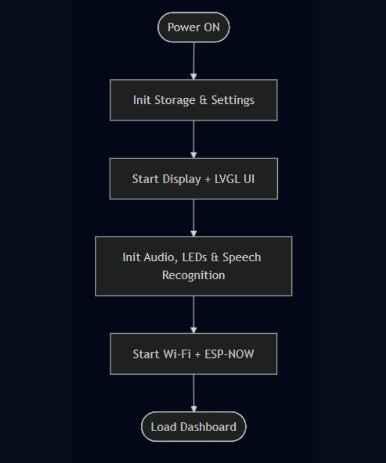
UI Startup Flow
Two key functions start the UI:
ui_main_start()
Runs after system boot.
Shows a custom boot screen.
Then calls:
ui_after_boot()
This function launches the main menu launcher.
From here user can open any screen.
ESP-NOW Communication (app_espnow.c)
The ESP32-S3 Box works as an ESP-NOW gateway.
It performs two wireless tasks:
- Receives sensor telemetry from Sensor Node
- Sends relay commands to Appliance Node
So this file implements bi-directional ESP-NOW communication.
- Wi-Fi Event → ESP-NOW Initialization
ESP-NOW requires Wi-Fi radio in Station mode.
Initialization is triggered when Wi-Fi starts.
static void wifi_event_handler(...) - Initialize ESP-NOW
esp_now_init(); - Register receive callback
esp_now_register_recv_cb(espnow_recv_cb); Now the hub can receive sensor packets.
- Add Relay Node as Peer
ESP-NOW requires peer MAC address. Declare Appliance node MAC address:
static uint8_t relay_peer_mac[6] = {0xC0,0x4E,0x30,0xEF,0x1E,0xAB}; //example
memcpy(peer.peer_addr, relay_peer_mac, 6); esp_now_add_peer(&peer);
This tells ESP32 where to send relay commands.
- Starting ESP-NOW System
void app_wifi_espnow_start(void) This function is called during system boot.
Set Wi-Fi station mode/Access point
esp_wifi_set_mode(WIFI_MODE_STA); Register Wi-Fi event handler
Start Wi-Fi radio
After Wi-Fi starts → event handler initializes ESP-NOW.
- Stopping ESP-NOW
Used when switching to Camera screen (Wi-Fi streaming).
void espnow_stop(void)
- ESP-NOW Transmit Function (Relay Control)
void espnow_send_relay_cmd(bool relay1, bool relay2) Called when user presses UI buttons.
- Create command packet & Send
cmd.appliance1 = relay1; cmd.appliance2 = relay2;esp_now_send(relay_peer_mac, &cmd, sizeof(cmd));Camera Streaming over HTTP (ESP32-CAM → ESP32-S3 BOX)
This module allows the ESP32-S3 Box to display live images from an ESP32-CAM without using the internet.
Instead of cloud streaming, the camera creates a local Wi-Fi Access Point, and the hub connects directly to it.
- Switching from ESP-NOW → Wi-Fi
ESP-NOW and Wi-Fi streaming cannot run together.
So when the Surveillance screen opens, the hub switches radio mode.
- Stop ESP-NOW
esp_now_deinit(); esp_wifi_stop(); This releases the Wi-Fi radio.
- Connect to ESP32-CAM Access Point
ESP32-CAM runs as:
SSID = ESP32-CAM
IP = 192.168.4.1
The hub connects as a Wi-Fi client:
wifi_config_t wifi_config = { .sta = { .ssid = "ESP32-CAM", .password = "", }, }; Then Wi-Fi is started and connected:
esp_wifi_start(); esp_wifi_connect();Only after IP is obtained, HTTP streaming can start.
- Downloading Image via HTTP
The ESP32-CAM provides a simple API:
This returns a JPEG image frame.
- HTTP Client Setup
esp_http_client_config_t config = { .url = "http://192.168.4.1/capture", }; Then the image is downloaded in chunks:
esp_http_client_read(...) The image is stored in jpeg_buf.
- Finding JPEG Start & End Markers
JPEG frames contain markers:
Marker Meaning:
FF D8Start of Image
FF D9End of Image
The function extract_jpeg() scans the stream and extracts the real JPEG frame.
- JPEG Decoding (TJpgDec Library)
The ESP32 cannot display JPEG directly.
LCD requires RGB565 raw pixels.
So we use Tiny JPEG Decoder (TJpgDec).
- Prepare decoder
jd_prepare(&jd, tjpgd_input, workbuf, ...); This initializes the JPEG decoder.
- Decompress JPEG
jd_decomp(&jd, tjpgd_output, 0); During decompression:
- Each JPEG block is decoded
- Converted from RGB888 → RGB565
- RGB Conversion
Inside output callback:
uint16_t rgb565 = ((r & 0xF8) << 8) | ((g & 0xFC) << 3) | ( b >> 3); This converts camera pixels into LCD format.
Result is stored in rgb_buf.
- Continuous Camera Task
Camera runs inside a FreeRTOS task.
while (cam_enabled) { download_photo(); decode_jpeg(); update_display(); delay(300ms); } So every ~300ms:
- Capture image
- Decode JPEG
- Display frame
This creates a live camera feed.
- Displaying Frame on Screen (LVGL)
LVGL needs an image descriptor:
static lv_img_dsc_t cam_img_dsc; After decoding:
cam_img_dsc.data = rgb_buf; lv_img_set_src(cam_img, &cam_img_dsc); This updates the screen with the new frame.
The process repeats → gives live video.
- Safe Start & Stop of Camera Task
cam_start(); Creates a FreeRTOS task pinned to Core 0.
- Stop camera when leaving screen
cam_stop();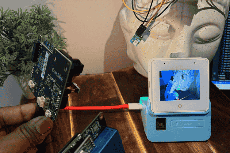
Voice Recognition & Command Execution (ESP-SR)
The ESP32-S3 Box uses Espressif Speech Recognition (ESP-SR) to enable fully offline voice control without internet.
Two main files are used from the factory demo:
app_sr.c - Speech recognition engine setup
app_sr_handler.cCommand processing & actions
Safe Start & Stop of Camera Task
- Wake Word Configuration (WakeNet)
The device first listens for a wake word before accepting commands.
- Setting the wake word
char *wn_name = esp_srmodel_filter(models, ESP_WN_PREFIX, (SR_LANG_EN == g_sr_data->lang ? "alexa" : "hilexin")); g_sr_data->afe_handle->set_wakenet(g_sr_data->afe_data, wn_name); - Loads WakeNet model from ESP-SR library
- Your English English wake word = “Alexa”
- Device continuously listens in low-power mode
- Voice interaction flow
Idle listening → Wake word detected → Listen for command → Execute action- Speech Recognition Task
Main SR Handler:
void sr_handler_task(void *pvParam) This task runs forever and processes voice results.
- Wait for recognition result
app_sr_get_result(&result, portMAX_DELAY); This blocks until:
- Wake word detected
- Command detected
- Timeout occurs
- Wake Word Detected
if (WAKENET_DETECTED == result.wakenet_mode) When wake word is heard:
Actions:
- Pause music/audio
- Play wake sound
- Show animation
- Ask user to speak command
User: "Alexa"
Device: "Say command"
- Command Recognition
When a command is detected:
const sr_cmd_t *cmd = app_sr_get_cmd_from_id(result.command_id);ESP-SR converts speech → command ID → text command.
Example:
"Turn AC ON" → SR_CMD_AC_ON- Executing Voice Commands
Commands are executed inside a switch statement.
Example commands: LED control, Music control, Custom actions
AC ON/OFF Command
case SR_CMD_AC_ON: ui_sensor_set_ac_poweron(); break;case SR_CMD_AC_OFF: ui_sensor_set_ac_poweroff(); break; These functions later trigger:
ESP-NOW → Relay Node → Appliance ON/OFF
So voice → wireless control → appliance.- Audio Feedback
The system provides voice feedback sounds:
sr_echo_play(AUDIO_WAKE); sr_echo_play(AUDIO_OK);IR Learning & Execution
This module enables the ESP32-S3 Box to:
- Learn IR commands from any remote
- Save them in flash memory
- Replay them on button press or voice command
This is implemented using the ESP-IDF RMT peripheral (Remote Control module).
- Starting IR Learning
static esp_err_t ir_learn_start(ir_learn_result_cb cb) This starts the IR learning engine.
Key configuration:
ir_learn_cfg_t ir_learn_config = { .learn_count = 4, .learn_gpio = BSP_IR_RX_GPIO, .resolution = 1MHz, }; - IR receiver pin enabled
- Captures high-resolution waveform (1µs precision)
- Learns the signal multiple times for accuracy
- IR Learning Callback
ir_learn_learn_send_callback(...) This function runs during the learning process.
It guides the user through steps:
- Learning flow
Ready → Press remote button → Capture signal → Verify → SaveIf both ON and OFF commands are captured successfully:
ir_learn_save_cfg(POWER_ON_PATH, &ir_leran_data_on); ir_learn_save_cfg(POWER_OFF_PATH, &ir_leran_data_off); The IR signals are saved to SPIFFS files.
- Saving Learned IR Signals
esp_err_t ir_learn_save_cfg(...) This writes IR waveform data to flash.
Saved data includes:
- Timing differences
- Number of IR pulses
- Raw RMT symbols
This allows the device to remember learned commands after reboot.
- Loading Saved IR Signals
esp_err_t ir_learn_read_cfg(...) At startup, saved IR commands are loaded back into memory.
So the user only needs to learn the remote once.
- Sending Learned IR Commands
static void ir_learn_test_tx_raw(...) This is the IR transmitter engine.
- Configure RMT TX channel
rmt_new_tx_channel(...) rmt_apply_carrier(... 38000 Hz ...) Creates the 38 kHz IR carrier frequency.
- Replay recorded waveform
rmt_transmit(tx_channel, nec_encoder, symbols, symbol_num, ...) This sends the exact waveform captured earlier.
- IR Transmit Task
static void ir_learn_test_tx_task(void *arg) This background task waits for commands:
xQueueReceive(rmt_out_queue, &tx_data, ...)- Voice Command -> IR Transmission
These functions connect speech recognition with IR.
Turn AC ON
esp_err_t ui_sensor_set_ac_poweron(void) Turn AC Off
esp_err_t ui_sensor_set_ac_poweroff(void) Both functions:
- Send IR waveform to transmit queue
- Update UI state
Example:
xQueueSendFromISR(rmt_out_queue, &ir_leran_read_on, 0); This is the bridge between voice and IR hardware.
- UI Button → Start Learning
ui_sensor_monitor_btn_ir_learning_event() Triggered when user presses Learn IR button.
Starts the learning process:
ir_learn_start(ir_learn_learn_send_callback);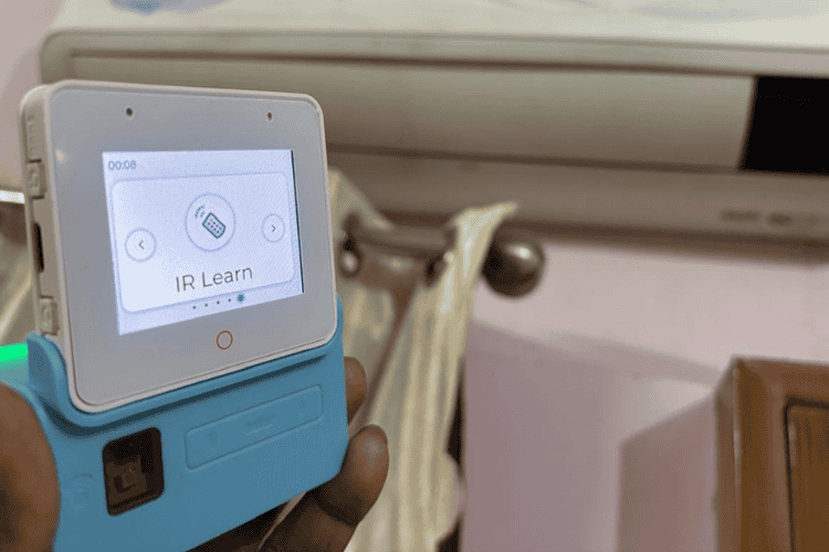
Radar Based Human Presence Wake-Up
The ESP32-S3 Box has an onboard mmWave radar sensor used to detect human presence.
This enables:
- Auto wake-up when user approaches
- Screen dimming when idle
- Animated “sleep face” when nobody is nearby
This makes the device feel alive.
- Idle Face UI Creation
static void ui_eyes_create(void) This function builds a full-screen animated face overlay using LVGL.
UI elements created:
- Black full-screen background
- Two animated eyes, controlled by a timer
- Smiling mouth drawn using canvas
- Enter Idle Mode (No Human Present)
static void idle_timeout_cb(lv_timer_t *t) Triggered when no activity is detected for some time.
Actions performed:
bsp_display_brightness_set(50); show_idle_eyes();- Exit Idle Mode (User Activity)
void ui_notify_activity(void) Called when:
- Touch input detected
- Voice detected
- Radar detects human
hide_idle_eyes(); bsp_display_brightness_set(100); lv_timer_reset(idle_timer);- Radar Polling Task
static void radar_poll_cb(lv_timer_t *t) This timer continuously checks radar sensor:
bool radar_now = bsp_board_get_sensor_handle()->get_radar_status(); When Human is detected
if (radar_now) { ui_notify_activity(); lv_timer_reset(idle_timer); } As long as a human is present:
- Idle timer keeps resetting
- Device NEVER goes to sleep
So the screen stays awake when someone is nearby.
Here is the app_main function call, which will execute all these tasks:
Please refer to the attached GitHub repository for the source code of the other nodes.
Conclusion
This project demonstrates how the ESP32-S3 Box can act as a complete local smart-home hub without relying on the internet or a router.
Using ESP-NOW, HTTP streaming, on-device voice recognition, IR learning, and radar-based presence detection, we transformed it into a fully functional offline smart home control system.
The final system brings together multiple embedded concepts into one product:
- Multi-node communication using ESP-NOW
- On-device AI voice control using ESP-SR
- Live camera streaming with JPEG decoding on the ESP32
- Real-time environmental monitoring
- Appliance control via relays and IR learning
- Human-presence wake-up using radar
- Modern touchscreen dashboard built with LVGL
All processing happens locally on the devices, ensuring privacy, low latency, and independence from cloud services.
In short, this project shows how far modern ESP32 hardware can go when multiple capabilities are combined into a single ecosystem.


