
Wireless communication is the future of technology! Communication established between two modules opens a large scope of applications. Wireless Transceivers modules come in very handy and are useful in such cases. RF transmitter and receiver, such as those used in our project, play a major role when it comes to communicating over long distances with a higher transmission data rate. XY - WA 2.4Ghz transceiver module is another radio frequency module that uses a license-free open ISM band and can transmit power up to 100mW with a high transmission rate of up to 1 Mbps at a transmission range up to 250m. RF modules are being widely used for wireless communication modes, you can also check out our other projects using different RF modules.
Hardware Section
We'll begin by discussing the module’s pin description, working, and its connections to a microcontroller. The module's working is also briefly described in this section.
Components used for XY-WA Radio Frequency Module
- XY - WA 2.4Ghz Transceiver module
- Arduino Uno
- Jumper wires
Pin Configuration of XY-WA Radio Frequency Module
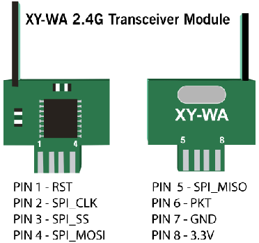
The image below describes the pin configuration of the XY-WA module used in our project. It is a Type A module and has 8 pins. It can be used to mount over custom circuit boards to reduce the size and make a compact device.
Wiring of the Radio Frequency Module with Arduino or MCU
The wiring of the XY-WA module is quite simple, as it uses a direct SPI interface and a few digital pins. The module can be hooked up to any microcontroller i.e. Arduino Uno, Mega, etc. The image below also represents a pictorial demonstration of the wiring of the XY-WA module to an Arduino Uno.

Pin connections are defined below:
XY- WA Radio Frequency module's simplified pin connections to the Arduino Uno microcontrollers are described below:
The reset pin (PIN 1) of the XY-WA module is connected to the 6th pin on the Arduino Uno microcontroller. CS pin(PIN 3) of the module is connected to the 5th pin of the Arduino Uno. Packet/Pkt (PIN 6) of the module is connected to the 4th pin of the Arduino Uno. Once these connections are made, we can connect the terminals for the SPI interface. MISO pin(PIN ) is connected to the 12th pin on the Arduino, MOSI pin(PIN ) is connected to the 11th pin on the Arduino, clock/CLK pin (PIN) is connected to the 13th pin on the Arduino. Whereas, the ground(PIN 7) and power 3.3V (PIN 8) are connected to the 7th and 8th pin of the Arduino Uno respectively.
Note: The XY-WA module comes in two variants or types i.e. Type A, which is the PCB welding type, and the other is Type B, which is the pin type. Here, we have used the Type A module. You can refer to the same pin connections by making sure the pin numbers in the right order.
To understand more about the pin configuration of the XY-WA module, you can follow the pin description table below.
IMPORTANT TABULATIONS
1. Some specifications about the module:
The table below shows some of the characteristics and the values of the following characteristics. Follow along, these may help to understand the module better.
|
Characteristics |
Value |
|
Operating Voltage |
2.2-3.6V |
|
Operating Temperature |
-40-85 degree C |
|
Emission Current |
15-24 mA |
|
Reception Current |
18 mA |
|
Sleep Current |
6 uA |
2. Pin Description of XY-WA 2.4Ghz:
The table below showcases the following pin number of the module XY-WA along with the description. This may help while making the connections with the Microcontroller.
|
PIN NUMBER |
DESCRIPTION |
|
PIN 1 |
RST (Reset) |
|
PIN 2 |
SPI_SCK |
|
PIN 3 |
SPI_SS |
|
PIN 4 |
SPI_MOSI |
|
PIN 5 |
SPI_MISO |
|
PIN 6 |
PKT |
|
PIN 7 |
GND |
|
PIN 8 |
3.3V |
HOW DOES XY-WA Module Work?
Radio Frequency:
2.4Ghz ISM band range is used in order to communicate between two peripherals. To communicate between two nodes using radio frequencies, it is important for both nodes to be on the same frequency band. Here, using XY-WA, the frequency range could be between 2.4Ghz to 2.525Ghz.
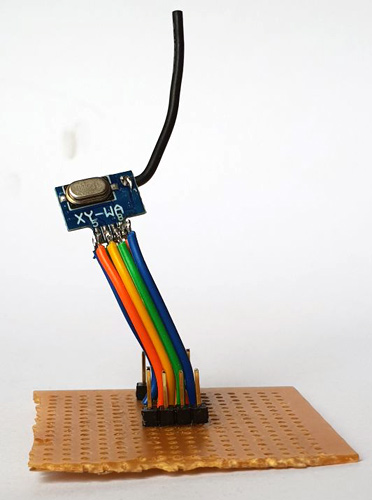
Here, I have soldered some jumper wires to the Zero board and connected male jumpers to it to make it convenient to connect it to the microcontroller.
Every channel on which two modules communicate occupies a bandwidth that is less than 1Mhz. Considering the frequency range of 2.4Ghz to 2.525Ghz, we get 125 possible channels.
You can use this formula to determine the frequency of the selected channel:
Frequency = 2400 + Channel selected
As there are 125 possible channels, you can use a value between 0 to 125 and put it in the channel selected value, and determine the frequency of the channel which will be used.
Since we will be dealing with the Radio Frequencies, there are certain pros and cons. Let's have a look at that:
Ways to increase the range of the XY - WA RF module:
- Increasing the transmitter module power. Most modules can be configured to send a custom output power, and a higher transmission power can be used to increase the range.
- Reducing the transmission data rate. A lower data rate over a channel can cover longer ranges.
- Changing the frequency channels could also serve as a great option since lower frequency bands are acquired by the Wi-Fi or other signals, shifting to a higher frequency band could remove any kind of interference thereby increasing the range.
Problems that could be faced while dealing with RF module:
- A bad power supply can not only hinder the range but also induce noises and lead to improper functioning of the module.
- A very low supply voltage can also become a problem at the transmitting and receiving ends. It is best to choose an adapter for these purposes as it will supply a stable output voltage supply.
- A low-quality antenna. These antennas would not hinder the true range potential of the module. The XY-WA comes with a built-in silicon antenna which allows a transmission power of 100mW.
Noise implications related to RF modules
When it comes to radio frequencies, RF signals are very susceptible to noise from different sources, one of which is its power input. DC batteries do get away with those, but if it is an AC-DC converter, using it probably will generate noise and affect the RF signals in terms of additive noise and low range.
Tips: 1. You can place a small capacitor across the power input of the module in order to physically isolate the XY-WA module.
2. You can also wind the MOSI and MISO wires around the ground wire of the module to reduce the noise.
Communication Protocol:
SPI interface:
Serial Peripheral Interface is primarily used for short-distance communication. It is a synchronous* serial data protocol that is used by multiple microcontrollers, microprocessors to communicate with various peripherals at higher speeds and over short distances. It is a full-duplex and a 4-wire communication.
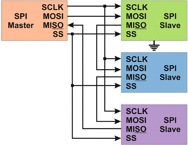
SPI communication contains a single master and can communicate with multiple slave nodes using SS pins(SS0, SS1, SS2,.....). The figure below explains how one master controls multiple slaves. Whichever slave has to be selected, a logic 0 is sent via the SS pin and that slave communicates with the master.
SPI has 4 modes of transmission, mode 0, mode1, mode 2, mode 3 are responsible for pushing the data in or out into the rising edge and falling edge of the clock signal which is called the Clock phase. These modes also tell when the clock is idle when high or low(called clock polarity). The table below shows how the modes combine polarity and phases together.
|
Mode |
Clock Polarity |
Clock Phase |
Output Edge |
Data Capture |
|
SPI_MODE 0 |
0 |
0 |
Falling |
Rising |
|
SPI_MODE 1 |
0 |
1 |
Rising |
Falling |
|
SPI_MODE 2 |
1 |
0 |
Rising |
Falling |
|
SPI_MODE 3 |
1 |
1 |
Falling |
Rising |
The major four common pins/ports in all SPI devices are defined below:
- MISO (Master In Slave Out): It is the Slave line to send the data to the master.
- MOSI (Master Out Slave In): It is the Master line to send the data to the multiple peripherals.
- SS (Slave Select): It is the pin that helps the master to decide which slave to choose and exchange data.
- SCK (Serial Clock): Since SPI is a synchronous communication mode, the serial clock pulses which are generated by the master helps to synchronize the communication channel.
*(Synchronous communication means that a clock signal is generated by the master to synchronize the data over a channel)
Software Section
In order to begin with the project, we would require some libraries.
- LT8920.h: (#include "LT8920.h”) LT8920.h library is used for LT8910/ LT8920 low-cost 2.4Ghz transceiver modules.
- SPI.h: (#include <SPI.h>) SPI.h library is used to communicate between Arduino and the Module.
Sample Code:
The following code can be used for both the modules since they are transceivers, hence anyone can either act as a transmitter and another as a receiver and vice versa.
The first step is to include the libraries, you can download the libraries from the above-mentioned links. SPI.h is used for the communication between the microcontroller and LT8920.h is used for the module. Also define the RST, CS, PKT pins are defined.
#include <SPI.h>
#include "LT8920.h"
const uint8_t PIN_NRF_RST = 6;  // Arduino Uno Pin = 6
const uint8_t PIN_NRF_CS = 5;  //Arduino Uno Pin = 5
const uint8_t PIN_NRF_PKT = 4; //Arduino Uno Pin = 4
                                                      // Similarly connect MISO = 12
                                                     // MOSI = 11  // SCK = 13
char sbuf[32];
LT8920 lt(PIN_NRF_CS, PIN_NRF_PKT, PIN_NRF_RST);
uint8_t a = 0;   //+1 with every packet recieved
uint8_t b = 105;    //Change from 0 to 255 in receiver and put other numbers
uint8_t c = 218;   //Check signal
uint8_t d = 53;   //reception / transmission
uint8_t e = 95;
void setup()
{
  Serial.begin(9600);
  SPI.begin();
  SPI.beginTransaction(SPISettings(12000000, MSBFIRST, SPI_MODE1));
  SPI.setClockDivider(SPI_CLOCK_DIV16);
  lt.begin();
  lt.writeRegister(35, 0x0F00);  //Setting the number of repeated dispatches to 255
  lt.setCurrentControl(255,255);  //Setting the power and gain
  lt.setDataRate(LT8920::LT8920_1MBPS);
  lt.setChannel(80);  // Setting the Channel
  lt.setSyncWord(0x123A123B123C123D);  //The receiver and transmitter must be on the same channel
}
void loop()
{
    uint8_t data[] = { a,b,c,d,e };
    lt.sendPacket(data,5);  //Sending the second digit in the number of words in the packet
    Serial.print("Packet send:");  // Printing “Packet send”
    Serial.println(a);
    a=a+1;
    if (a>=256)
    {
      a=0;
    }
      lt.startListening();  //We switch to the reception part
      delay(1000);
   if (lt.available())
    {
      uint8_t buf[32];
      int packetSize = lt.read(buf, 32);
      if (packetSize > 0)
      {
        Serial.println(F("Packet read OK")); // If packet received print “Packet read OK”
        for(int i = 0; i < packetSize; i++)
        {
          Serial.print(i);
          Serial.print("=");
          Serial.println(buf[i]);
        }
      }
   }
     else
      {
        Serial.println(F("Packet read --"));
      }
}
A huge shout out to Olegmih’s YouTube channel and his code for this module. You can check out his YouTube channel for more details. Google drive link for Olegmih’s code.
https://drive.google.com/file/d/1l9dug_XT4s2RBVhKsfcMAz7I4Z6gg242/view
Testing of the XY-WA Radio Frequency Module
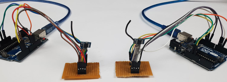
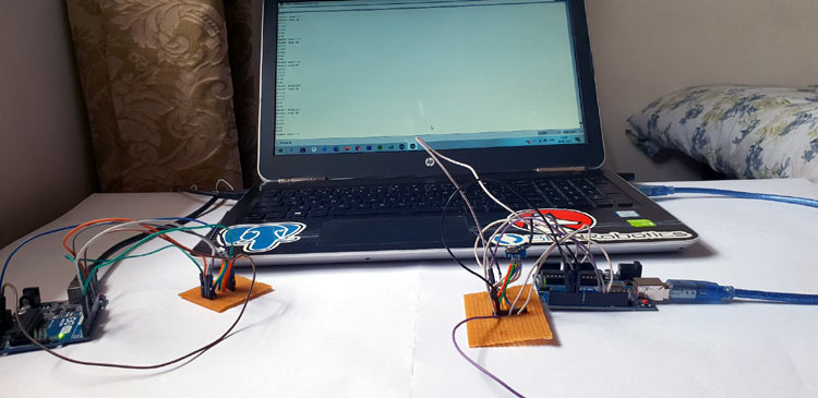
Below, I have hooked both the Radio Frequency modules to the Arduino and then connected them to the laptop. The code was then uploaded to both the modules and the serial monitor was observed. As per the print commands described in the code, we observe that the packets are now being sent and received by the RF modules.
I hope you all enjoyed this project, and if you have any questions related to the project, please feel free to upload them to our Forum and we will get back to you as soon as possible. Thanks!
For further clarification, you can also follow the video below:
Complete Project Code
#include <SPI.h>
#include "LT8920.h"
const uint8_t PIN_NRF_RST = 6;        // Arduino Uno Pin = 6
const uint8_t PIN_NRF_CS = 5;         //Arduino Uno Pin = 5
const uint8_t PIN_NRF_PKT = 4;        //Arduino Uno Pin = 4
                                         // Similarly connect MISO = 12
              // MOSI = 11                   // SCK = 13
char sbuf[32];
LT8920 lt(PIN_NRF_CS, PIN_NRF_PKT, PIN_NRF_RST);

uint8_t a = 0;                         //+1 with every packet recieved
uint8_t b = 105;                       //Change from 0 to 255 in receiver and put other numbers
uint8_t c = 218;                       //Check signal
uint8_t d = 53;                        //reception / transmission
uint8_t e = 95;
void setup()
{
  Serial.begin(9600);
  SPI.begin();
  SPI.beginTransaction(SPISettings(12000000, MSBFIRST, SPI_MODE1));
  SPI.setClockDivider(SPI_CLOCK_DIV16);
  lt.begin();
  lt.writeRegister(35, 0x0F00);        //Setting the number of repeated dispatches to 255
  lt.setCurrentControl(255,255);       //Setting the power and gain
  lt.setDataRate(LT8920::LT8920_1MBPS);
  lt.setChannel(80);                   // Setting the Channel
  lt.setSyncWord(0x123A123B123C123D);  //The receiver and transmitter must be on the same channel

}
void loop()
{
    uint8_t data[] = { a,b,c,d,e };
    lt.sendPacket(data,5);                 //Sending the second digit in the number of words in the packet
    Serial.print("Packet send:");  // Printing “Packet send”
    Serial.println(a);
    a=a+1;
    if (a>=256)
    {
      a=0;
    }
      lt.startListening();                 //We switch to the reception part
      delay(1000);
   if (lt.available())
    {
      uint8_t buf[32];
      int packetSize = lt.read(buf, 32);
      if (packetSize > 0)
      {
        Serial.println(F("Packet read OK")); // If packet received print “Packet read OK”
        for(int i = 0; i < packetSize; i++)
        {
          Serial.print(i);
          Serial.print("=");
          Serial.println(buf[i]);
        }
      }
   }
     else
      {
        Serial.println(F("Packet read --"));
      }
}