

In this tutorial we are going to design an 8x8 LED Matrix Scrolling Display using ATMEGA32, which will show scrolling alphabets.
8x8 LED Matrix contains 64 LEDs (Light Emitting Diodes) which are arranged in the form of a matrix, hence the name is LED matrix. We are going to make this Matrix by soldering 64 LEDs on to the perfboard or DOT PCB. The LEDs can be of any color, choose the ones which are available with you. Then we will write a C program for ATmega32 AVR Microcontroller to control these 64 LEDs matrix. The ATmega, according to program, powers appropriate LEDs to show characters in scrolling fashion. We have previously done same Scrolling Text project with Arduino.
Components Required:
- ATMEGA32
- Power supply (5v)
- 64 LEDs
- 1KΩ resistors (8 pieces),
- AVR ISP Programmer
- Perfboard with other soldering tools
- ATMEL STUDIO 6.1
Circuit and Working Explanation:
There are 64 LEDs arranged in a matrix form. So we have 8 columns and 8 rows. Over those rows and columns, all the positive terminals in a row are brought together. For each row, there is one Common Positive Terminal for all 8 LED in that row. It is shown in below figure,
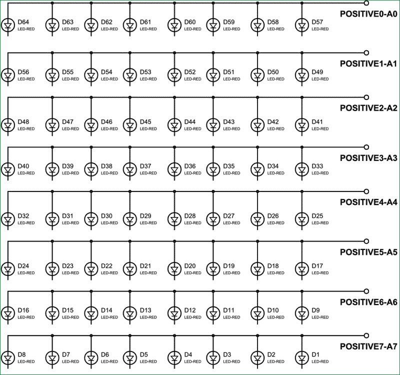
So for 8 rows we have 8 common positive terminals. Consider the first row, as seen in the figure, 8 LEDs from D57 to D64 have a common positive terminal and are denoted by ‘POSITIVE0’. Now if we want glow one or all LEDs in the first ROW of matrix, then we should power the A0 of LED Matrix. Likewise if we want to glow any LED (or all) in any ROW then we need to power the corresponding Common Positive Terminal Pin of that respective Row.
This is not over yet and just leaving the MATRIX ROWS with positive supply will not yield anything. We need to ground the LEDs negatives to glow them. So in 8x8 LED matrix, all the negative terminals of the LEDs in any column are brought together to form eight Common Negative Terminals, like all the negative terminals in first column are connected together to the C7 (NEGATIVE7). This is shown in below figure:
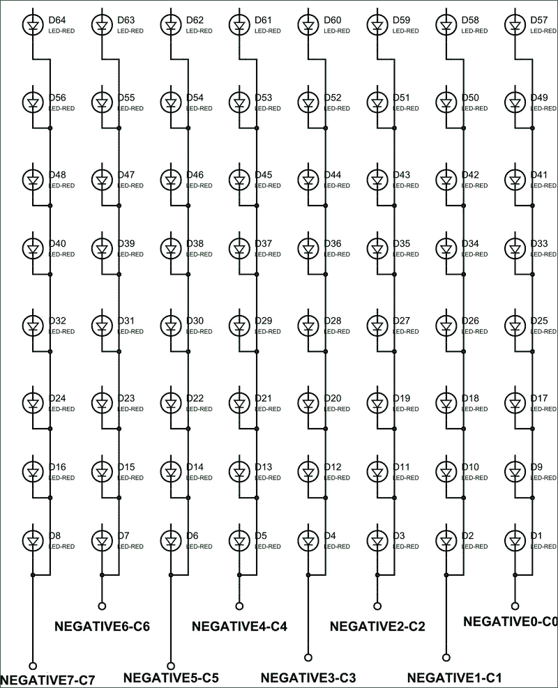
One should pay attention to these pins while soldering the LEDs on Perfboard.
Now if we need to ground any LED in the first column then we will ground the PIN-C7 (NEGATIVE7) of the MATRIX, and it will ground all the LEDs in first column. The same process goes for all the other seven common negative columns.
Since now you know how Common Positive and Common Negative works. Let’s put them together to see how they work together and the final Circuit for Scrolling 8x8 LED Matrix display will look like this:

Driving 8x8 LED Matrix using Multiplexing:
Now let’s say we want to turn ON LED57 then we need to power PORTA0 of ATMEGA32 and ground the PORTC0 of ATMEGA32. Now for turning both LED57 and LED50 on, we need to power PINA0, PINA1 and ground PINC0, PINC1. But doing so will not only turn on D57, D50 but also D49, D58. To avoid that we use a technique called Multiplexing. We have already discussed this Multiplex Technique in 8x8 LED Matrix in detail; go through that article for detailed explanation. Here we are explaining the Multiplexing briefly.
The human eye cannot capture a frequency more than 30 HZ. That is if a LED goes ON and OFF continuously at the rate of 30HZ or more. The eye sees the LED as continuously ON. However this is not the case and LED will be actually turning ON and OFF constantly. This technique is called Multiplexing.
Let’s say for example, we want to only turn on LED57 and LED50 without turning on D49 and D58. Trick is, we will first provide power to first row to turn ON LED57 and wait for 1mSEC, and then we will turn it OFF. Then we will provide power to second row to turn on LED50 and wait for 1mSEC then will turn it OFF. The cycle goes continuously with high frequency and LED57 & LED50 will getting On and Off rapidly and both the LEDs will appear to be continuously ON to our eye. Means we are only providing power to the one row at a time, eliminating the chances of turning on other LEDs in other rows. We will use this technique to show all characters.
We will write decimal value for each character and we will program these values into the ATMEGA32. The program shifts these values from left to right continuously showing scrolling characters.
Generally MAX7219 IC is used to drive the 8x8 LED Matrix, we have used that IC in our previous project with Arduino: check here.
Programming Explanation:
Full code has been given below the article, we have written the C program for ATmega32 for scrolling the characters horizontally on 8x8 LED matrix.
To change the characters to be displayed, just replace the value in the char ALPHA[] array according to the character values given below,
{0,0b01111111,0b11111111,0b11001100,0b11001100,0b11001100,0b11111111,0b01111111}, //A
{0,0b00111100,0b01111110,0b11011011,0b11011011,0b11011011,0b11111111,0b11111111}, //B
{0,0b11000011,0b11000011,0b11000011,0b11000011,0b11100111,0b01111110,0b00111100}, //C
{0,0b01111110,0b10111101,0b11000011,0b11000011,0b11000011,0b11111111,0b11111111}, //D
{0,0b11011011,0b11011011,0b11011011,0b11011011,0b11011011,0b11111111,0b11111111}, //E
{0,0b11011000,0b11011000,0b11011000,0b11011000,0b11011000,0b11111111,0b11111111}, //F
{0b00011111,0b11011111,0b11011000,0b11011011,0b11011011,0b11011011,0b11111111,0b11111111}, //G
{0,0b11111111,0b11111111,0b00011000,0b00011000,0b00011000,0b11111111,0b11111111}, //H
{0b11000011,0b11000011,0b11000011,0b11111111,0b11111111,0b11000011,0b11000011,0b11000011}, //I
{0b11000000,0b11000000,0b11000000,0b11111111,0b11111111,0b11000011,0b11001111,0b11001111}, //J
{0,0b11000011,0b11100111,0b01111110,0b00111100,0b00011000,0b11111111,0b11111111}, //K
{0b00000011,0b00000011,0b00000011,0b00000011,0b00000011,0b00000011,0b11111111,0b11111111}, //L
{0b11111111,0b11111111,0b01100000,0b01110000,0b01110000,0b01100000,0b11111111,0b11111111}, //M
{0b11111111,0b11111111,0b00011100,0b00111000,0b01110000,0b11100000,0b11111111,0b11111111}, //N
{0b01111110,0b11111111,0b11000011,0b11000011,0b11000011,0b11000011,0b11111111,0b01111110}, //O
{0,0b01110000,0b11111000,0b11001100,0b11001100,0b11001100,0b11111111,0b11111111}, //P
{0b01111110,0b11111111,0b11001111,0b11011111,0b11011011,0b11000011,0b11111111,0b01111110}, //Q
{0b01111001,0b11111011,0b11011111,0b11011110,0b11011100,0b11011000,0b11111111,0b11111111}, //R
{0b11001110,0b11011111,0b11011011,0b11011011,0b11011011,0b11011011,0b11111011,0b01110011}, //S
{0b11000000,0b11000000,0b11000000,0b11111111,0b11111111,0b11000000,0b11000000,0b11000000}, //T
{0b11111110,0b11111111,0b00000011,0b00000011,0b00000011,0b00000011,0b11111111,0b11111110}, //U
{0b11100000,0b11111100,0b00011110,0b00000011,0b00000011,0b00011110,0b11111100,0b11100000}, //V
{0b11111110,0b11111111,0b00000011,0b11111111,0b11111111,0b00000011,0b11111111,0b11111110}, //W
{0b01000010,0b11100111,0b01111110,0b00111100,0b00111100,0b01111110,0b11100111,0b01000010}, //X
{0b01000000,0b11100000,0b01110000,0b00111111,0b00111111,0b01110000,0b11100000,0b01000000}, //Y
{0b11000011,0b11100011,0b11110011,0b11111011,0b11011111,0b11001111,0b11000111,0b11000011}  //Z
Like if you want to display DAD on the LED Matrix then first replace the Characters values in the char ALPHA[] array by putting values for characters D,A and D from the above list:
char ALPHA[] = {0,0,0,0,0,0,0,0,0,0,0,
0,0b01111110,0b10111101,0b11000011,0b11000011,0b11000011,0b11111111,0b11111111,
0,0b01111111,0b11111111,0b11001100,0b11001100,0b11001100,0b11111111,0b01111111,
0,0b01111110,0b10111101,0b11000011,0b11000011,0b11000011,0b11111111,0b11111111,
0,0,0,0,0,0,0,0,0,0,0};
Total values are now 5*10=50 values, so
Replace,
  for(int x=0;x<142;x++) //150-8(to stop overflow)
  {……..

With,
  for(int x=0;x<42;x++) //50-8(to stop overflow)
  {……..
So you just need to change the number.
With this you have done the programming and now you can Scroll any text on the 8x8 LED Matrix with AVR, check the Full code below with a demonstration Video.
Complete Project Code
#include <avr/io.h>      //IO header
#define F_CPU 11059200UL //defining crystal frequency
#include <util/delay.h>  //delay header
int main(void)
{
    DDRD = 0xFF; //PORTD as output
    DDRA = 0xFF; //PORTA as output
    DDRC = 0xFF; //PORTC as output

char ALPHA[]={0,0,0,0,0,0,0,0,0,0,0,
    0,0b11000011,0b11000011,0b11000011,0b11000011,0b11100111,0b01111110,0b00111100,0,0,
    0b11000011,0b11000011,0b11000011,0b11111111,0b11111111,0b11000011,0b11000011,0b11000011,0,0,
    0b01111001,0b11111011,0b11011111,0b11011110,0b11011100,0b11011000,0b11111111,0b11111111    ,0,0,
    0,0b11000011,0b11000011,0b11000011,0b11000011,0b11100111,0b01111110,0b00111100,0,0,
    0b11111110,0b11111111,0b00000011,0b00000011,0b00000011,0b00000011,0b11111111,0b11111110,0,0,
    0b11000011,0b11000011,0b11000011,0b11111111,0b11111111,0b11000011,0b11000011,0b11000011,0,0,
    0b11000000,0b11000000,0b11000000,0b11111111,0b11111111,0b11000000,0b11000000,0b11000000,0,0,
    0,0b01111110,0b10111101,0b11000011,0b11000011,0b11000011,0b11111111,0b11111111,0,0,
    0b11000011,0b11000011,0b11000011,0b11111111,0b11111111,0b11000011,0b11000011,0b11000011,0,0,
    0b00011111,0b11011111,0b11011000,0b11011011,0b11011011,0b11011011,0b11111111,0b11111111,0,0,
    0,0b11011011,0b11011011,0b11011011,0b11011011,0b11011011,0b11111111,0b11111111,0,0,
    0b11001110,0b11011111,0b11011011,0b11011011,0b11011011,0b11011011,0b11111011,0b01110011,0,0,
    0b11000000,0b11000000,0b11000000,0b11111111,0b11111111,0b11000000,0b11000000,0b11000000,0,0,
    0,0,0,0,0,0,0,0,0,0,0,
    };
    char PORT[8] = {1,2,4,8,16,32,64,128}; //pin values of a port 2^0,2^1,2^2……2^7
        uint8_t l =0;

    while(1)
    {
        // there are 142 values in the set of ALPHA to display 'CIRCUIT DIGEST', then shift them after each loop execution
        for(int x=0;x<142;x++)
        {
                for(int a=0;a<20;a++) //show each character 20 times before shifting a column
                {

                    for (int i=0;i<8;i++)
                    {
                        PORTC = ~PORT[i];    //ground the PORTC pin
                        PORTA = ALPHA[i+x];  //power the PORTA
                        _delay_ms(1);
                        PORTC = PORT[i];     //clear pin after 1msec
                    }

                }
    }
        }
}

I want to know that how we can upload the program to the chip ? For which component is used ?