

In this project we are going to design an 8x8 LED matrix display, for that we are going to interface an 8x8 LED matrix module with Arduino Uno. An 8x8 LED matrix contains 64 LEDs (Light Emitting Diodes) which are arranged in the form of a matrix, hence the name LED matrix.
These matrixes can be made by circuiting 64 LEDs, however that process is time consuming. Now a day they are available in compact forms as shown in below image. These compact modules are available in different sizes and many colors. The cost of module is same as cost of 64 LEDs, so for hobbyists this is easiest to work on.
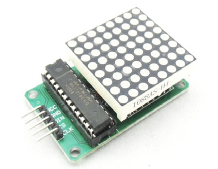
The bare LED matrix has 16 pin outs with 8 common positive and another 8 common negative. For connecting this matrix directly to a UNO, we need to spare 16 pins on the UNO. With the output pins low on UNO, we cannot spare 16 PINS. So we need to connect this matrix to a driver chip. This driver chip along with matrix comes as a set which is shown in below figure.
This module will be interfaced with Arduino for displaying alphabets, hence the matrix display. First of all for interfacing LED matrix with Arduino, we need to download a library specifically designed for LED MATRIX. This library will be available at: https://github.com/shaai/Arduino_LED_matrix_sketch/archive/master.zip
After downloading the Zip file, extract the contents to ARDUINO folder. (Go to local disk where ARDUINO NIGHTLY software is installed, open the folder, search for folder named “library”, extract the contents of zip file in that folder, restart the program you will now be able to use features for matrix interface)
Components Required
Hardware: Arduino Uno, Power supply (5v), 100 uF capacitor (connected across power supply)
Software: Arduino Nightly
Circuit Diagram and Explanation
The connections which are done between Arduino Uno and LED matrix module is shown in below table.
PIN2 ------------------LOAD or CHIPSELECT of LED module
PIN3------------------CLOCK of LED module
PIN4 ------------------DATAIN of LED module
+5V ------------------VCC of LED module
GND ------------------GND of LED module
The circuit diagram of 8*8 LED matrix display is shown in below figure.

Now for using the special futures called by installing new library, we need to establish few commands in program and are stated below.
#include "LedControlMS.h" #define NBR_MTX 1 LedControl lc=LedControl(4,3,2, NBR_MTX); lc.writeString(0,"CIRCUITDIGEST"); lc.clearAll(); |
First we need to call the header file for interfacing a LED matrix to Arduino Uno. That is” #include "LedControlMS.h"”, this header file call the library special functions.
We have a feature with these modules we can connect many number of modules in series and program them together as a single display. This feature comes in handy when we need a display unit which could display multiple characters at a time. So we need to tell the controller how many displays we are connecting.
In this module there are mainly three pins; data flow from UNO to module takes places with these three pins. The pins are DATAIN (data receiving pin), CLOCK (clock pin), and CHIPSELECT (command receiving pin).
Now we need to tell the UNO where we are connecting these pins. This is done by command “LedControl lc=LedControl(4,3,2, NBR_MTX); ”. “lc.writeString(0,"CIRCUITDIGEST");”, this command is used for telling UNO which characters are to be displayed on the LED matrix. With the above the display shows” CIRCUITDIGEST”, with each character once.
We need to clear the display chip memory before sending any other data, this is done by command ” lc.clearAll();".
By this way we can easily interface a 8x8 LED matrix to Arduino Uno.
Complete Project Code
// Arduino 8x8 LED Matrix Code
#include "LedControlMS.h"
 //pin 4 is connected to the DataIn
// pin 3 is connected to the CLK
 //pin 2 is connected to LOAD

#define NBR_MTX 1 //number of matrices attached is one
LedControl lc=LedControl(4,3,2, NBR_MTX);//

void setup()
{
  for (int i=0; i< NBR_MTX; i++)
  {
    lc.shutdown(i,false);
  /* Set the brightness to a medium values */
    lc.setIntensity(i,8);
  /* and clear the display */
    lc.clearDisplay(i);
                delay(100);
  }
}

void loop()
{
                  lc.writeString(0,"CIRCUITDIGEST");//sending characters to display
                  lc.clearAll();//clearing the display
                  delay(1000);
}
Comments
need a useful pragram to display"WELCOME TO E&TC DEPT." on 8*8 LED.Also tell how many no of LED's will be needed
Hi
How do you rotate the text. i have 4 in 1dmd
hi, please I have not succeeded to simulate on proteus the following is the error send by isis after trying simulation''invalid opcode 0*9419 at pc =0C=16''
This very line of the code, lc.writeString(0, "CIRCUITDIGEST"), refused to be compiled. Please review the code, and tell me where I got it all wrong, your assistance is in indeed needed. thanks
Ardunio

Hello there, i need to interface five 8 by 8 LED matrix Displays to an Arduino micro controller, the LED display has 24 control pins what interface shall i use...help me out please