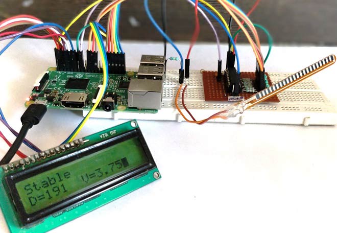
Raspberry Pi is an ARM architecture processor based board designed for electronic engineers and hobbyists. The PI is one of most trusted project development platforms out there now. With higher processor speed and 1 GB RAM, the PI can be used for many high profile projects like Image processing and Internet of Things. There are a lot of cool things that can be done with a PI, but one sad feature is that it does not have an inbuilt ADC module.
Only, if the Raspberry Pi could be interfaced with sensors it can get to know about the real world parameters and interact with it. Most of the sensors out there are analog sensor and hence we should learn to use an external ADC module IC with Raspberry Pi to interface these sensors. In this project we will learn how we can Interface Flex Sensor with Raspberry Pi and Display its Values on LCD Screen. We have also covered how to interface flex sensor with Arduino, you can also check out that tutorial if intrested.
Material Required:
- Raspberry Pi (Any Model)
- ADC0804 IC
- 16*2 LCD display
- Flex Sensor
- Resistors and capacitors
- Breadboard or perf board.
ADC0804 Single Channel 8-bit ADC module:
Before we proceed any further, let us learn about this ADC0804 IC and how to use this with raspberry pi. ADC0804 is a single channel 8-bit IC, meaning it can read a single ADC value and map it to 8-bit of digital data. These 8-bit digital data can be read by the Raspberry Pi, thus the value will be 0-255 since 2^8 is 256. As shown in the pinouts of the IC below, the pins DB0 to DB7 are used to read these digital values.
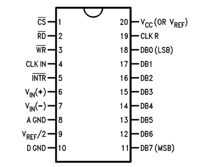
Now another important thing here is, the ADC0804 operates at 5V and so it provides output in 5V logic signal. In 8 pin output (representing 8bits), every pin provides +5V output to represent logic ’1’. So the problem is the PI logic is of +3.3v, so you cannot give +5V logic to the +3.3V GPIO pin of PI. If you give +5V to any GPIO pin of PI, the board gets damaged.
So to step-down logic level from +5V, we will be using voltage divider circuit. We have discussed Voltage Divider Circuit previously look into it for further clarification. What we will do is, we use two resistors to divide +5V logic into 2*2.5V logics. So after division we will give +2.5v logic to Raspberry Pi. So, whenever logic ‘1’ is presented by ADC0804 we will see +2.5V at the PI GPIO Pin, instead of +5V. Learn more about ADC here: Introduction to ADC0804.
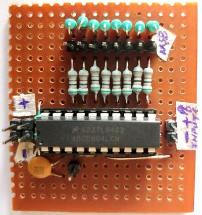
Below is the picture of ADC Module using ADC0804 that we have built on Perf Board:
Circuit Diagram and Explanation:
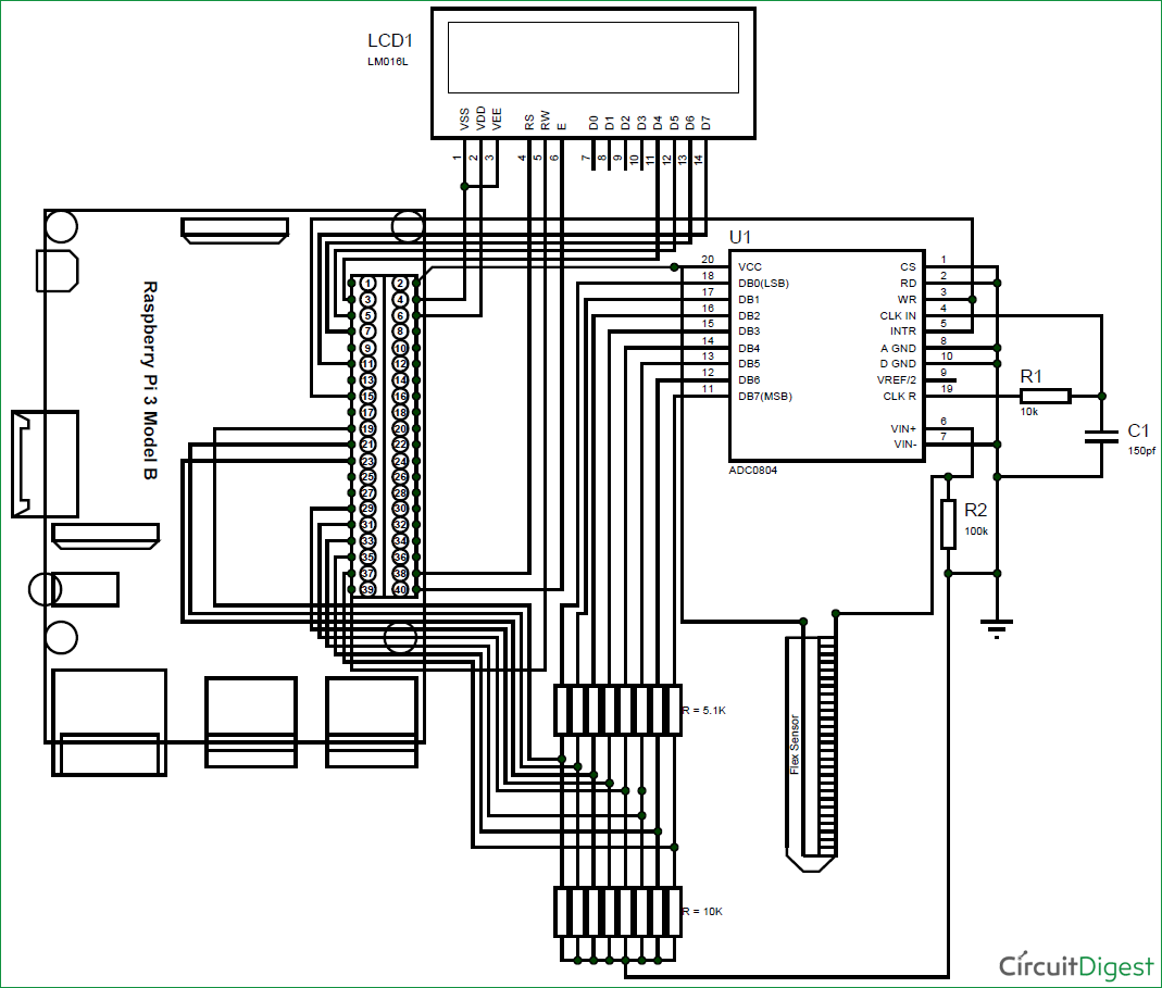
The complete circuit diagram for interfacing Flex Sensor with Raspberry Pi is shown below. The explanation of the same is as follows.
This raspberry pi flex sensor circuit might seem to be a bit complex with lots of wires, but if you take a closer look most of the wires are directly connected from the LCD and 8-bit data pin to the Raspberry pi. The following table will help you while making and verifying the connections.
Pin name | Raspberry Pin number | Raspberry Pi GPIO name |
LCD Vss | Pin 4 | Ground |
LCD Vdd | Pin 6 | Vcc (+5V) |
LCD Vee | Pin 4 | Ground |
LCD Rs | Pin 38 | GPIO 20 |
LCD RW | Pin 39 | Ground |
LCD E | Pin 40 | GPIO 21 |
LCD D4 | Pin 3 | GPIO 2 |
LCD D5 | Pin 5 | GPIO 3 |
LCD D6 | Pin 7 | GPIO 4 |
LCD D7 | Pin 11 | GPIO 17 |
ADC0804 Vcc | Pin 2 | Vcc (+5V) |
ADC0804 B0 | Pin 19 (through 5.1K) | GPIO 10 |
ADC0804 B1 | Pin 21 (through 5.1K) | GPIO 9 |
ADC0804 B2 | Pin 23 (through 5.1K) | GPIO 11 |
ADC0804 B3 | Pin 29 (through 5.1K) | GPIO 5 |
ADC0804 B4 | Pin 31 (through 5.1K) | GPIO 6 |
ADC0804 B5 | Pin 33 (through 5.1K) | GPIO 13 |
ADC0804 B6 | Pin 35 (through 5.1K) | GPIO 19 |
ADC0804 B7 | Pin 37 (through 5.1K) | GPIO 26 |
ADC0804 WR/INTR | Pin 15 | GPIO 22 |
You can use the following picture to determine the pin numbers on Raspberry since.

Like all ADC modules, the ADC0804 IC also requires a clock signal to operate, luckily this IC has an internal clock source, so we just have to add the RC circuit to the CLK in and CLK R pins as shown in the circuit. We have used a value of 10K and 105pf, but we can use any value close like 1uf, 0.1uf, 0.01uf should also work.
Then to connect the Flex sensor we have used a potential divider circuit using a 100K resistor. As the Flex sensor is bent the resistance across it will vary and so will the potential drop across the resistor. This drop is measured by the ADC0804 IC and 8-bit data is generated accordingly.
Check other projects related to Flex Sensor:
- Flex Sensor Interfacing with AVR Microcontroller
- Arduino based Angry Bird Game Controller using Flex Sensor
- Servo Motor Control by Flex Sensor
- Generating Tones by Tapping Fingers using Arduino
Programming the Raspberry Pi:
Once we are done with the connections, we should read the status of these 8-bits using Raspberry Pi and convert them to Decimal so that we can make use of them. The program for doing the same and displaying the resulting values on the LCD screen is given at the end of this page. Further the code is explained into small junks below.
We need an LCD library to interface LCD with Pi. For this we use the library developed by shubham which will help us to interface a 16*2 LCD display with a Pi in four wire mode. Also we need libraries to make use of time and Pi GPIO pins.
Note: The lcd.py should be downloaded from here, and placed in the same directory where this program is saved. Only then the code will compile.
import lcd #Import the LCD library by [email protected]
import time #Import time
import RPi.GPIO as GPIO #GPIO will be reffered as GPIO only
The LCD pin definitions are assigned to the variables as shown below. Note that these numbers are the GPIO pin numbers and not the actual pin numbers. You can use the table above to compare GPIO numbers with pin numbers. The array binary will include all the data pin numbers and the array bits will store the resulting value of all the GPIO pins.
#LCD pin definitions
D4=2
D5=3
D6=4
D7=17
RS=20
EN=21
binarys = (10,9,11,5,6,13,19,26) #Array of pin numbers connect to DB0-DB7
bits = [0,0,0,0,0,0,0,0] #resulting values of 8-bit data
Now, we have to define the input and output pins. The seven data pins will be the input pin and the trigger pin (RST and INTR) will be the output pin. We can read the 8-bit data values from input pin only if we trigger the output pin high for a particular time according to the datasheet. Since we have declared the binary pins in binarys array we can use a for loop for declaration as shown below.
for binary in binarys:
    GPIO.setup(binary, GPIO.IN) #All binary pins are input pins
  #Trigger pin
    GPIO.setup(22, GPIO.OUT) #WR and INTR pins are output
Now using the LCD library commands we can initialize the LCD module and display a small intro message as shown below.
mylcd=lcd.lcd()
mylcd.begin(D4,D5,D6,D7,RS,EN)
#Intro Message
mylcd.Print("Flex Sensor with")
mylcd.setCursor(2,1)
mylcd.Print("Raspberry Pi")
time.sleep(2)
mylcd.clear()
Inside the infinite while loop, we start reading the binary values convert them to decimal and update the result on LCD. As said earlier before we read the ADC values we should make the trigger pin to be high for a particular time to activate the ADC conversion. This is done by using the following lines.
  GPIO.output(22, 1) #Turn ON Trigger
    time.sleep(0.1)
    GPIO.output(22, 0) #Turn OFF Trigger
Now, we should read the 8-data pins and update the result in the bits array. To do this we use a for loop to compare each input pin with True and False. If true the respective bits array will be made as 1 else it will be made as 0. This was all the 8-bit data will be made 0 and 1 respective of the values read.
#Read the input pins and update result in bit array
    for i in range(8):
        if(GPIO.input(binarys[i]) == True):
            bits[i] = 1
        if(GPIO.input(binarys[i]) == False):
            bits[i] = 0
Once we have updated the bits array, we should convert this array to decimal value. This is nothing but binary to decimal conversion. For 8-bit binary data 2^8 is 256. So we will get decimal data from 0 to 255. In python the operator “**” is used to find the power of any value. Since bits[0] starts with MSB we multiply it with 2^(7-position). This way we can convert all the binary values to decimal data and then display it on the LCD
    #calculate the decimal value using bit array
               for i in range(8):
        decimal = decimal + (bits[i] * (2**(7-i)))
Once we know the decimal value it is easy to calculate the voltage value. We just have to multiply it with 19.63. Because for a 8-bit 5VADC each bit is an analogy of 19.3 milli volt. The resulting voltage value is the value of voltage that has appeared across the pins Vin+ and Vin- of the ADC0804 IC.
   #calculate voltage value
    Voltage = decimal * 19.63 *0.001 #one unit is 19.3mV
Using the value of voltage we can determine how the flex sensor has been bent and in what direction it has been bent. In the below lines I have just compared the read voltage values with predetermined values of voltage to indicate the position of the Flex sensor on the LCD screen.
#compare voltage and display status of sensor
               mylcd.setCursor(1,1)
    if (Voltage>3.8):
        mylcd.Print("Bent Forward")
    elif (Voltage<3.5):
        mylcd.Print("Bent Backward")
    else:
        mylcd.Print("Stable")
Similarly you can use the voltage value to perform any task that you wish the Raspberry Pi to perform.
Showing Flex Sensor value on LCD using Raspberry Pi:
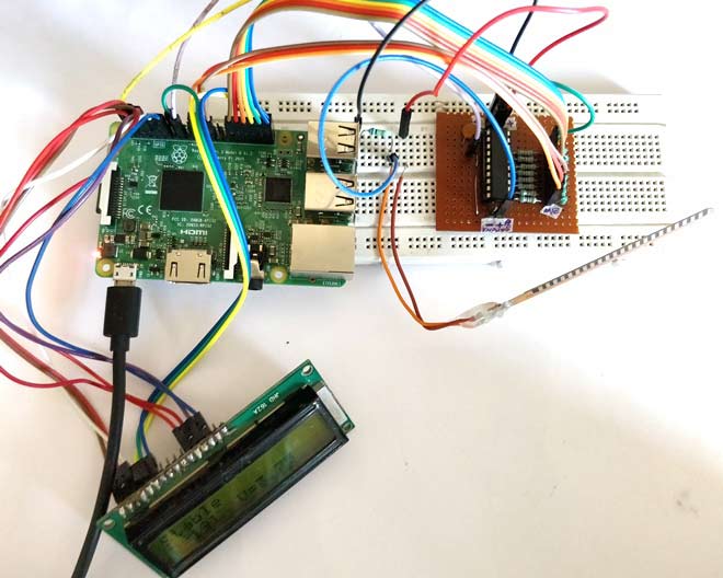
The working of the project is very simple. But make sure you have downloaded the lcd.py header file and have placed it in the same directory where your current program is present. Then make the connections are shown in the circuit diagram using a breadboard or a perf board and run the below program on your Pi and you should get thing working. You set up should look something like this below.
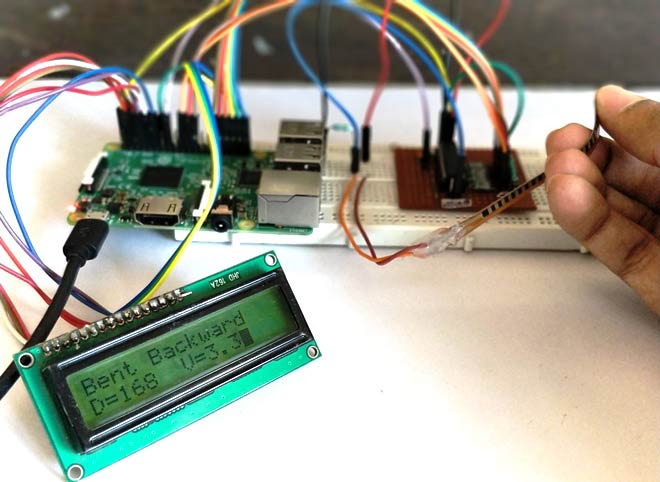
As shown the LCD will display the Decimal value, voltage value and sensor position. Just bend the sensor forward or backward and you should be able to see the voltage and decimal value getting varied, also a status text will be displayed. You can connect any sensor and notice the Voltage across it getting varied.
The complete working of the tutorial can be found at the video given below. Hope you understood the project and enjoyed building something similar. If you have any doubt, leave them in the comment section or on the forums and I will try my best in answering them.
Complete Project Code
import lcd #Import the LCD library by electro-passionindia
import time #Import time
import RPi.GPIO as GPIO #GPIO will be referred as GPIO only

GPIO.setmode(GPIO.BCM)
GPIO.setwarnings(False)

#LCD pin definitions
D4=2
D5=3
D6=4
D7=17
RS=20
EN=21

binarys = (10,9,11,5,6,13,19,26) #Array of pin numbers connect to DB0-DB7


bits = [0,0,0,0,0,0,0,0] #resulting values of 8-bit data


for binary in binarys:
    GPIO.setup(binary, GPIO.IN) #All binary pins are input pins

  #Trigger pin
    GPIO.setup(22, GPIO.OUT) #WR and INTR pins are output


mylcd=lcd.lcd()
mylcd.begin(D4,D5,D6,D7,RS,EN)

#Intro Message
mylcd.Print("Flex Sensor with")
mylcd.setCursor(2,1)
mylcd.Print("Raspberry Pi")
time.sleep(2)
mylcd.clear()

while 1:

    decimal = Voltage = 0 #intitialize to zero

    GPIO.output(22, 1) #Turn ON Trigger
    time.sleep(0.1)
    GPIO.output(22, 0) #Turn OFF Trigger
    mylcd.clear()

#Read the input pins and update result in bit array
    for i in range(8):
        if(GPIO.input(binarys[i]) == True):
            bits[i] = 1
        if(GPIO.input(binarys[i]) == False):
            bits[i] = 0

#print binary values if required for debugging
##    mylcd.Print("Binary= ")
##    mylcd.setCursor(1,8)
##    for i in range(8):
##        mylcd.Print(bits[i])

    #calculate the decimal value using bit array
for i in range(8):
        decimal = decimal + (bits[i] * (2**(7-i)))

#Display decimal value
    mylcd.setCursor(2,1)
    mylcd.Print("D=")
    mylcd.setCursor(2,3)
    mylcd.Print(decimal)

#calculate voltage value
    Voltage = decimal * 19.63 *0.001 #one unit is 19.3mV

    #compare voltage and display status of sensor
mylcd.setCursor(1,1)
    if (Voltage>3.8):
        mylcd.Print("Bent Forward")
    elif (Voltage<3.5):
        mylcd.Print("Bent Backward")
    else:
        mylcd.Print("Stable")

    Voltage = str(round(Voltage,2)) #limit to two digit after decimal

    #display voltage
mylcd.setCursor(2,8)
    mylcd.Print("V=")
    mylcd.setCursor(2,10)
    mylcd.Print(Voltage)


    time.sleep(0.5) #relaxing time
Comments
Yes Mark, so true. It is not a good idea to use Sensors involving ADC directly on Pi. It is a waste of resource. This project is just to help people understand how to do ADC using Pi if at all needed. Who knows! there might be an application where we need only one sensor interfaced to Pi and the rest alll takes places through USB and CAM, in that case it will not be a good idea to bring in a MCU just to make one ADC conversion.
I am trying this without LCD, I am not getting a stable output.
I am using this code.
import time #Import time
import RPi.GPIO as GPIO #GPIO will be referred as GPIO only
GPIO.setmode(GPIO.BCM)
GPIO.setwarnings(False)
binarys = (10,9,11,5,6,13,19,26) #Array of pin numbers connect to DB0-DB7
bits = [0,0,0,0,0,0,0,0] #resulting values of 8-bit data
for binary in binarys:
GPIO.setup(binary, GPIO.IN) #All binary pins are input pins
#Trigger pin
GPIO.setup(22, GPIO.OUT) #WR and INTR pins are output
while 1:
decimal = 0 #intitialize to zero
GPIO.output(22, 1) #Turn ON Trigger
time.sleep(0.1)
GPIO.output(22, 0) #Turn OFF Trigger
#Read the input pins and update result in bit array
for i in range(8):
if(GPIO.input(binarys[i]) == True):
bits[i] = 1
if(GPIO.input(binarys[i]) == False):
bits[i] = 0
for i in range(8):
decimal = decimal + (bits[i] * (2**(7-i)))
print decimal
time.sleep(0.5) #relaxing time
What if I want to interface more than one flex sensor what will b the changes in code n output
Did you get the solution for this ? if yes, then please do share.
How do I connect multiple sensors in the same way along with some others as well like contact sensors and accelerometer ?
It is not a good idea to use ADC IC if you are measuring more than two ADC values as it will occupy all the GPIO pins.
So the best way is to use a microcontroller like Arduino. You can connect all the sensors to this MCU read their values and then send their values serially (I2C/SPI/USART) to the Pi and then do whatever you want with those values in the PI side
to use multiple flex sensors mcp3008 because it is a 8 channel 10 bit ADC ic,
here ADC used is single channel



Great job. Well explained. But it might be easier to use a microcontroller instead of a microprocessor, like the Arduino. It was made for sensors. It has an already built in A/D converter which can be multiplexed. And it already deals with 5 volt sensors without conversion. Just a thought.