
By Angel Lalu
Smart home systems are increasingly adopting intelligent sensing technologies to understand indoor environments and automatically adapt to the user's needs. Among these technologies, cameras play a critical role in tasks such as human presence detection, room occupancy monitoring, and context-aware automation for lighting, climate control, and energy management. However, the deployment of cameras inside private living spaces introduces significant privacy concerns, as conventional smart home systems often store or transmit raw visual data that can expose sensitive personal activities.
The Privacy-Preserving Smart Home Camera System addresses this challenge by rethinking the role of cameras in smart environments. Instead of capturing, storing, or transmitting images or video, the system performs all visual processing locally on the device and extracts only high-level semantic information, such as motion intensity and occupancy status. These semantic signals are sufficient for intelligent automation while eliminating the risks associated with visual data leakage. By combining edge computing with lightweight IoT communication, the proposed system demonstrates how camera-based sensing can be integrated into smart homes in a responsible, privacy-aware manner without compromising functionality.
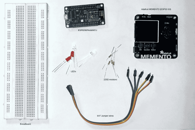
Components Required
| Component Name | Quantity | Datasheet/Link |
| LED | 4 | View Datasheet |
| Memento Diy Camera Main Board | 1 | View Datasheet |
| Jumpper Wire | 1 | View Datasheet |
| ESP8266 NodeMCU | 1 | View Datasheet |
| Breadboard | 1 | View Datasheet |
| 220Ω Resistor | 4 | View Datasheet |
Circuit Diagram

The circuit diagram for this project was created using Circuit Designer (app.cirkitdesigner.com) and later refined using Canva to make it clearer and easier to understand. Circuit Designer was used to place the components and define their connections, while Canva was used to improve labelling and overall presentation.
The system is built around two main units: the Adafruit MEMENTO (ESP32-S3) and the ESP8266/NodeMCU, which communicate with each other via UDP over a local network (WiFi). The Adafruit MEMENTO acts as the smart home camera and the main processing unit. It uses its onboard camera to observe the environment and processes all data locally on the device. Instead of storing or transmitting images or video, the board extracts only meaningful information such as room occupancy, activity level, engagement, and drowsiness. These semantic signals are then sent as UDP packets to the ESP8266.
The ESP8266/NodeMCU serves as the indicator and automation unit. LEDs are connected to their GPIO pins through 220 Ω current-limiting resistors, with all grounds connected. Each LED represents a specific smart home condition, such as occupancy detection, smart lamp status, engagement level, or a drowsy state. Based on the semantic signals received through UDP, the ESP8266 updates the LEDs to reflect what is happening in the room.
Overall, this circuit design keeps sensing and output clearly separated. By exchanging only high-level semantic information through lightweight UDP messages and keeping all visual data on the camera device, the system enables smart home automation while maintaining user privacy.
Hardware Assembly
Step 1: Mount the Adafruit MEMENTO (ESP32-S3)
Secure the Adafruit MEMENTO on a non-conductive surface or inside a plastic enclosure to avoid electrical shorts. Position the board so that the onboard camera faces the monitored area with no physical obstructions, glare sources, or excessive backlighting.
Step 2: Power and configure the Adafruit MEMENTO
Connect the MEMENTO to a stable power source (USB or regulated supply) and upload the firmware responsible for camera initialisation, image preprocessing, and on-device semantic inference. Verify that the camera initialises correctly and that no raw images or video are stored.
Step 3: Mount and wire the ESP8266/NodeMCU with LEDs
Place the ESP8266/NodeMCU on a separate non-conductive surface to clearly isolate it from the camera unit. Connect each LED to a dedicated GPIO pin through a 220 Ω current-limiting resistor, and connect all LED cathodes and the ESP8266 ground to a common ground rail.
Step 4: Establish Wi-Fi connectivity for both boards
Configure both the ESP32-S3 and ESP8266 to connect to the same local Wi-Fi network. Assign fixed IP addresses or known ports as required to ensure reliable UDP packet exchange without routing through external networks.
Step 5: Configure UDP transmission on the Adafruit MEMENTO
Program the ESP32-S3 to package semantic outputs such as room occupancy, activity level, engagement, and drowsiness into lightweight UDP messages. Transmit only these abstract values at defined intervals or event triggers, ensuring no visual data leaves the device.
Step 6: Configure UDP reception and LED control on the ESP8266
Implement a UDP listener on the ESP8266 that parses incoming semantic packets from the MEMENTO. Based on the received values, drive the corresponding GPIO pins high or low to illuminate LEDs representing different smart home states.
Step 7: System power-up and validation
Power on both boards and observe LED behaviour while performing real-world actions in the monitored area. Confirm that LED responses correctly reflect semantic events such as presence, activity changes, or drowsiness, validating end-to-end operation.
Code Explanation
System Overview
This project presents a privacy-preserving smart home camera system that performs on-device visual understanding without storing or transmitting any images or video. Instead of acting as a recorder, the camera functions as a semantic sensor, extracting high-level information such as occupancy, activity level, posture, fatigue, engagement, and safety risks. Only these abstract semantic signals are shared with a secondary control unit over a local network, ensuring strong privacy guarantees.
The system is implemented using a dual-device architecture: an Adafruit MEMENTO (ESP32-S3) for vision sensing and inference, and an ESP8266/NodeMCU for actuation and user feedback through LEDs.
Implementation Details
The program is written for the Adafruit MEMENTO (ESP32-S3) and implements a privacy-preserving smart-home semantic camera.
It explicitly avoids image storage, video recording, or cloud communication.(The entire code is available in the GitHub Repository below.)
The required libraries are imported for time handling, memory management, Wi-Fi communication, UDP networking, and camera access.
import time
import gc
import wifi
import socketpool
import adafruit_pycamera
The Wi-Fi credentials and UDP communication parameters are defined. The UDP target IP corresponds to the local indicator/control device.
WIFI_SSID = "YOUR WIFI"
WIFI_PASS = "YOUR PASSWORD"
UDP_TARGET_IP = "192.168.0.168"
UDP_PORT = 5005
(Note: udp target ip changes according to the WiFi local IP it is important to check which ip is used with the help of serial mointor)
The ESP32-S3 connects to the local network and initializes a UDP socket for lightweight data transmission.
wifi.radio.enabled = True
wifi.radio.connect(WIFI_SSID, WIFI_PASS)
pool = socketpool.SocketPool(wifi.radio)
sock = pool.socket(pool.AF_INET, pool.SOCK_DGRAM)
The onboard camera is configured for low-resolution grayscale capture, and the camera LED is disabled to reduce visual intrusion.
pycam = adafruit_pycamera.PyCamera()
pycam.mode = 0
pycam.resolution = 1   # 320x240
pycam.effect = 2     # Black & white
pycam.led_level = 0
System parameters are defined to control frame rate, subsampling, smoothing, and temporal analysis windows.
FRAME_INTERVAL = 1.0
SUBSAMPLE_STEP = 10
WINDOW = 6
POSTURE_WINDOW = 5
OCCUPANCY_THRESHOLD = 8
MOTION_ALPHA = 0.4
The frame_difference() function computes motion energy by comparing pixel differences between consecutive frames.
def frame_difference(a, b):
 total = 0
 count = 0
 for y in range(0, a.height, SUBSAMPLE_STEP):
   for x in range(0, a.width, SUBSAMPLE_STEP):
     total += abs(a[x, y] - b[x, y])
     count += 1
 return total // count if count else 0
Motion values are adaptively normalized to a 0–100 scale and smoothed using an exponential moving average.
def normalize_motion(raw):
 global motion_min, motion_max
 if motion_min is None or raw < motion_min:
   motion_min = raw
 if motion_max is None or raw > motion_max:
   motion_max = raw
 span = max(1, motion_max - motion_min)
 return int(100 * (raw - motion_min) / span)
def smooth_motion(m):
 global motion_smooth
 if motion_smooth is None:
   motion_smooth = m
 else:
   motion_smooth = MOTION_ALPHA * m + (1 - MOTION_ALPHA) * motion_smooth
 return int(motion_smooth)
The vertical centroid of brightness is calculated to estimate posture in a geometry-based.
def compute_centroid_y(frame):
 total = 0
 weighted = 0
 for y in range(0, frame.height, SUBSAMPLE_STEP):
   for x in range(0, frame.width, SUBSAMPLE_STEP):
     val = frame[x, y]
     if val > 20:
       weighted += y * val
       total += val
 return weighted // total if total else None
Semantic state functions convert low-level signals into high-level meanings such as activity, posture, engagement, comfort, and drowsiness.
def activity_level(m):
 if m < 25:
   return "IDLE"
 elif m < 60:
   return "ACTIVE"
 return "INTENSE"
def drowsy_flag(history):
 if len(history) < WINDOW:
   return False
 return max(history[-WINDOW:]) < 15
In the main loop, frames are captured, processed, and immediately discarded after analysis.
frame = pycam.continuous_capture()
Semantic states are computed and packaged into a compact, human-readable UDP payload.
payload = (
 f"OCC={int(occupied)},"
 f"MOTION={motion},"
 f"ACT={activity},"
 f"POST={posture},"
 f"ENG={engagement},"
 f"COMF={comfort},"
 f"DROWSY={int(drowsy)}"
)- The semantic payload is transmitted over UDP, and no visual data is retained.
sock.sendto(payload.encode(), (UDP_TARGET_IP, UDP_PORT)) - Garbage collection is explicitly triggered, and the loop timing is controlled to maintain a fixed sampling rate.
gc.collect()
time.sleep(FRAME_INTERVAL)
1. Vision Acquisition and On-Device Processing
The Adafruit MEMENTO serves as the primary sensing and intelligence unit. It uses its onboard camera in grayscale, low-resolution mode to reduce data volume and eliminate identifiable visual details. Two processing approaches are demonstrated:
TinyML-based inference (C++ / Arduino) using a quantized INT8 CNN for face and mask classification, executed entirely on the ESP32-S3 using TensorFlow Lite Micro.
Non-ML semantic vision (CircuitPython) using lightweight signal processing techniques such as frame differencing, centroid estimation, motion smoothing, and temporal filtering.
From raw frames, the system derives low-level signals (motion energy, vertical centroid, motion trends) and converts them into high-level semantic states including posture (standing/sitting/lying), activity intensity, affective state, fatigue level, responsiveness, and safety conditions like fall risk or unresponsiveness.
At no point are images stored or streamed - frames exist only momentarily in RAM and are immediately discarded after analysis.
2. Semantic Communication over UDP
Once semantic inference is complete, the ESP32-S3 packages the results into a compact, human-readable UDP payload and broadcasts it over a local Wi-Fi network. The transmitted data contains only abstract labels and numeric indicators (e.g., occupancy, motion level, posture, fatigue), not visual information.
This design keeps communication lightweight, low-latency, and privacy-safe, while enabling real-time smart home responses.
3. Embedded Control and Actuation Unit
The ESP8266/NodeMCU acts as the automation and indicator module. It listens for incoming UDP packets and updates connected LEDs to reflect the current state of the environment:
- Occupancy detection
- Engagement or restlessness
- Drowsiness or fatigue
- Smart lighting behavior (simulated via PWM brightness control)
Failsafe mechanisms are included so that if communication is lost, all indicators reset to a safe state. This separation of sensing and actuation improves modularity and system reliability.
Firmware for ESP8266 Indicator and Actuation Module
#include <ESP8266WiFi.h>
#include <WiFiUdp.h>
// =====================
// WIFI CONFIG
// =====================
const char* ssid = "YOUR WIFI";
const char* password = "YOUR PASSWORD";
// =====================
// UDP CONFIG
// =====================
WiFiUDP udp;
const unsigned int localPort = 5005;
char packetBuffer[350];
// =====================
// LED GPIOs (4 LEDs)
// =====================
#define LED_LAMP 4 // D2 White lamp (PWM)
#define LED_OCC 12 // D6 White occupancy
#define LED_DROWSY 5 // D1 Red drowsy
#define LED_ENG 13 // D7 Red engagement
// =====================
// STATE
// =====================
unsigned long lastPacketTime = 0;
const unsigned long UDP_TIMEOUT = 5000;
int restlessCount = 0;
// Lamp brightness levels (tuned for 220Ω)
const int LAMP_OFF = 0;
const int LAMP_DIM = 180;
const int LAMP_FULL = 450;
// =====================
void allOff() {
digitalWrite(LED_OCC, LOW);
digitalWrite(LED_DROWSY, LOW);
digitalWrite(LED_ENG, LOW);
analogWrite(LED_LAMP, LAMP_OFF);
restlessCount = 0;
}
// =====================
void setup() {
Serial.begin(115200);
Serial.println("\nESP UDP LED Controller (Final, Comfort Tuned)");
pinMode(LED_LAMP, OUTPUT);
pinMode(LED_OCC, OUTPUT);
pinMode(LED_DROWSY, OUTPUT);
pinMode(LED_ENG, OUTPUT);
allOff();
WiFi.begin(ssid, password);
Serial.print("Connecting WiFi");
while (WiFi.status() != WL_CONNECTED) {
delay(500);
Serial.print(".");
}
Serial.println("\nWiFi connected");
Serial.print("ESP IP: ");
Serial.println(WiFi.localIP());
udp.begin(localPort);
Serial.print("UDP listening on port ");
Serial.println(localPort);
}
// =====================
void loop() {
if (WiFi.status() != WL_CONNECTED) {
WiFi.reconnect();
}
int packetSize = udp.parsePacket();
if (!packetSize) {
// ---- FAILSAFE ----
if (millis() - lastPacketTime > UDP_TIMEOUT) {
allOff();
}
return;
}
int len = udp.read(packetBuffer, sizeof(packetBuffer) - 1);
if (len <= 0) return;
packetBuffer[len] = '\0';
String msg = String(packetBuffer);
lastPacketTime = millis();
Serial.print("UDP >>> ");
Serial.println(msg);
// =====================
// OCCUPANCY MASTER
// =====================
bool occupied = msg.indexOf("OCC=1") >= 0;
if (!occupied) {
allOff();
return;
}
// Room occupied
digitalWrite(LED_OCC, HIGH);
// =====================
// DROWSY
// =====================
bool drowsy = msg.indexOf("DROWSY=1") >= 0;
digitalWrite(LED_DROWSY, drowsy ? HIGH : LOW);
// =====================
// ENGAGEMENT (HYSTERESIS)
// =====================
if (msg.indexOf("ENG=RESTLESS") >= 0 ||
msg.indexOf("ENG=PASSIVE") >= 0) {
restlessCount++;
} else {
restlessCount = 0;
}
digitalWrite(LED_ENG, restlessCount >= 2 ? HIGH : LOW);
// =====================
// PSEUDO LAMP CONTROL
// =====================
if (drowsy) {
analogWrite(LED_LAMP, LAMP_DIM); // dim, calming light
} else {
analogWrite(LED_LAMP, LAMP_FULL); // comfortable brightness
}
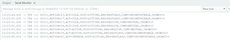
}Output In Serial Monitors
The serial output shown represents the semantic information generated by the privacy-preserving smart home camera. Each line corresponds to one processing cycle and summarizes the system’s understanding of the scene using abstract parameters instead of raw visual data.
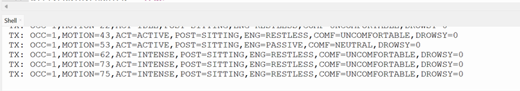
The ESP8266 recevies the same parameters through UDP which helps in controlling the output.
Key Features and Innovations
1. Privacy by Architecture
No video storage, no cloud processing, no image transmission
Visual data never leaves the camera device
Only semantic metadata is shared
2. Fully Edge-Based Intelligence
Runs entirely on low-power microcontrollers
Demonstrates both TinyML inference and non-ML semantic vision
Works without GPUs, servers, or internet access
3. Rich Semantic Understanding
Goes beyond motion detection to infer posture, fatigue, engagement, affect, and safety
Temporal reasoning using sliding windows and trend analysis
Self-calibrating motion normalization for different rooms and lighting
4. Modular & Scalable Design
Clear separation between vision sensing and actuation
Additional smart home devices can be added by subscribing to the same UDP data
Suitable for assisted living, elder care, and adaptive environments
5. Low-Cost and Energy Efficient
Uses off-the-shelf microcontroller boards
Minimal computation and bandwidth requirements
Designed for continuous, long-term deployment
GitHub Repository


