
An Arduino hourglass project is a fun and educational project that involves creating a digital hourglass timer using an Arduino microcontroller and some simple electronic components. The project combines programming, electronics, and mechanics to create a functional timer that can be used for various purposes.
You can check out other such cool Arduino projects like this on our website
Materials needed
- Arduino Pro Mini
- MPU6050 accelerometer
- LED matrix display MAX71219
- TP4056 lithium battery charging module
- Lithium-polymer battery
- Tactile switch
- Laser-cut acrylic parts
- Wires
- Soldering iron and solder
- Laser cutter (or maybe a laser-cut shop nearby)
- Solid modeling software
- Computer with Arduino IDE installed
Before diving into building the project let’s first understand some of the important modules which are needed to build this project.
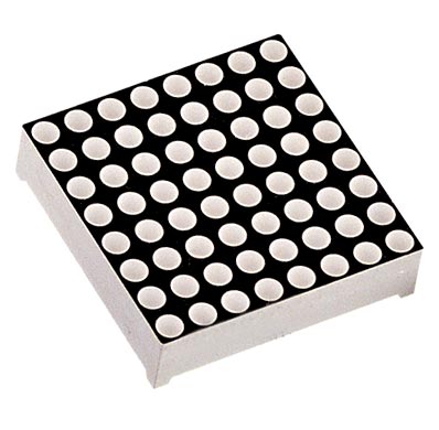
MAX71219 8x8 LED Matrix Display
An 8X8 LED matrix is used to display different kinds of information. The LED matrices are available in various types like single color, multicolor and they come in all kinds of sizes like 8x8, 16x16, 32x32, etc.
The internal circuit diagram of an 8x8 led matrix looks like this
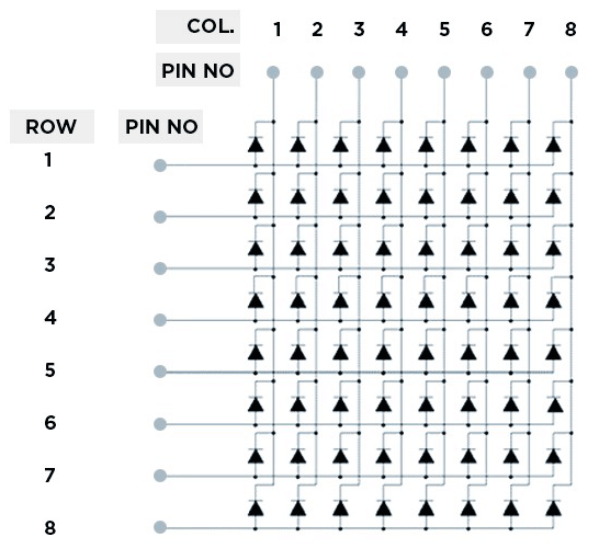
As you can see that the led matrix has 8 row pins and 8 column pins to control specific leds. When these row-column pins are given signal through external microcontroller, the specific led blinks. For more info on working of the MAX71219 display you can refer to our website.
MAX71219 LED Display Driver
If we connect this 8X8 led matrix directly to a microcontroller like Arduino, the Arduino will be busy the whole time sending data to the led matrix and refreshing the display and will not have time to do other tasks. But by integrating a small chip called as the MAX71219, you don’t need to worry about that because the IC will take care of that.
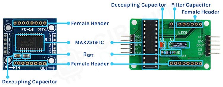
There are two kinds of 8x8 LED Matrix which are available in the market. The driver board for both of these boards look like this. There’s not much of a difference between the pinout or use case of these drivers except its IC package (the left one is the SMD version of the same board while the right one is the DIP). You can use whichever one you want.
Pinout of 8X8 LED Matrix
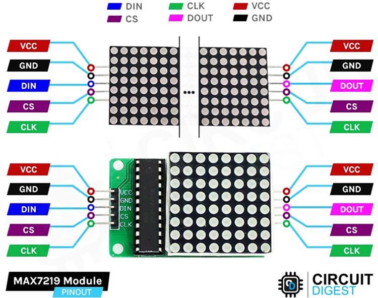
VCC Power supply pin for the MAX7219. Typically connected to a positive power source (5V).
GND Ground pin for the MAX7219. Connected to the negative terminal of the power source and ground reference.
DIN Data In pin. This pin receives the serial data from the microcontroller or data source.
CS Chip Select pin. This pin is used to enable or disable the MAX7219 for data transfer.
CLK Clock pin. This pin receives the clock signal from the microcontroller to synchronize data transmission.
LOAD/CS Load or Chip Select pin. This pin is used to latch the data from the serial input.
DOUT Data Out pin. This pin is optional and can be used for cascading multiple MAX7219 drivers together
Commonly asked questions about MAX7129 8x8 LED Matrix Display
How do I connect and control an 8x8 LED matrix with the MAX7219?
Answer: Connect VCC and GND pins of the MAX7219 to the power supply. Connect DIN, CS, and CLK pins to the microcontroller. Use the MAX7219 library and send appropriate commands to display desired patterns or characters on the LED matrix.
How can I change the brightness of the LED matrix with the MAX7219?
Answer: Use the MAX7219 library function to set the brightness level. The brightness can typically be adjusted on a scale of 0 to 15, with 0 being the lowest and 15 the highest. Sending the appropriate command to the MAX7219 will adjust the brightness accordingly.
Can I cascade multiple MAX7219 drivers to control multiple 8x8 LED matrices?
Answer: Yes, the MAX7219 supports cascading multiple drivers. Connect the DOUT pin of one MAX7219 to the DIN pin of the next MAX7219. Ensure each MAX7219 has a unique CS pin. By sending appropriate commands to each MAX7219, you can control multiple LED matrices simultaneously.
Now that we understand the led matrix device. Let’s try to create this project step by step.
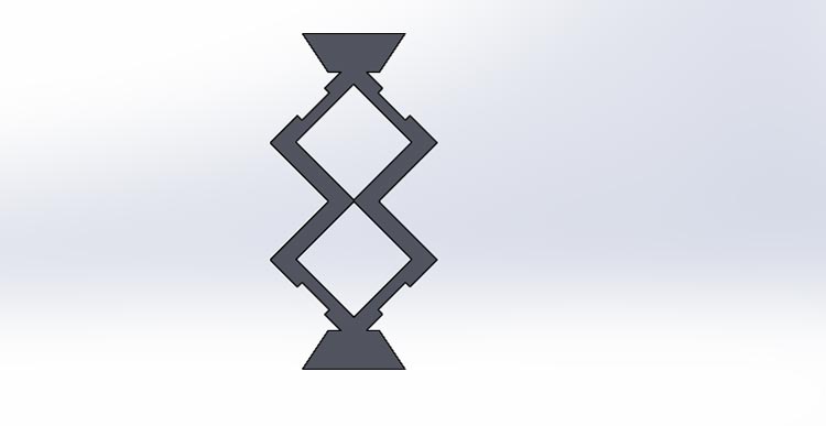
Design the Hourglass
Design the Hourglass using any solid modeling software, design the front plate, back plate, and supporting plates. Export the design files in a compatible format for laser cutting.
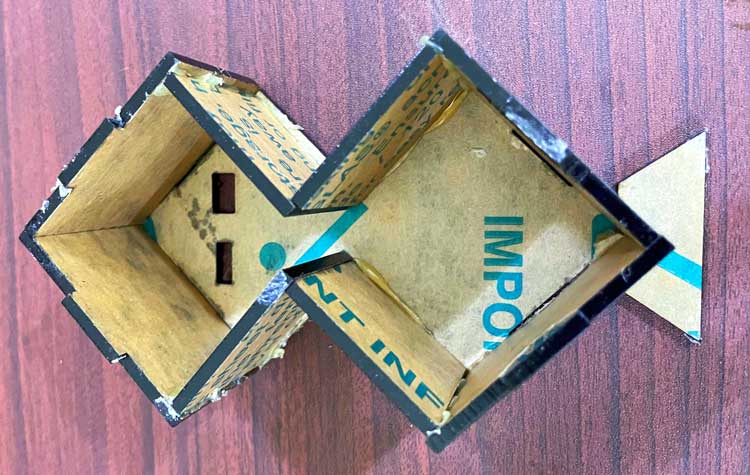
Assemble the Acrylic Plates
Take the back plate and attach the other supporting plates to it.
Circuit Diagram

The circuit diagram above is how you connect the complete hourglass. You can refer it to recreate the project.
Arduino Code
Upload the Code Using the Arduino IDE. The complete code can be found at the absolute bottom of the blog.
Before we start to upload the code, we first need to sort the libraries issue which is the most common while making this project. You can download all the software files here.
Extract the files given in this zip file.
Go to hourglass-main>src folder and you will find all the dependent libraries there.
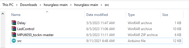
Just extract them and copy and paste the folders in the libraries folder of your documents
(Path:-your pc name> my documents>Arduino>libraries)
Now when that is done, you can press the upload button on the Arduino IDE
Final Assembly and Testing
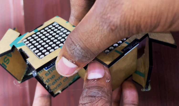
Insert the lithium-polymer battery into the hourglass Attach the front plate to the back plate using adhesive. Turn the switch on.
Congratulations, you've successfully created an Arduino-based hourglass.
Projects using Arduino Pro Mini

Drawing inspiration from the groundbreaking product showcased on Shark Tank, Torchit, our creation combines technology and compassion to empower the visually impaired. By integrating ultrasonic sensors, a haptic feedback system, and intuitive controls, this intelligent assistive device enhances mobility and safety for individuals with visual challenges.

Explore the world of audio customization with our Arduino-based project utilizing the JQ6500 MP3 Module. This hands-on endeavor enables you to create personalized sound effects through a user-friendly interface. Whether you're looking to enhance a small gathering or add flair to your DIY ventures, our comprehensive guide will assist you in programming the Arduino and seamlessly integrating the JQ6500 MP3 Module

Introducing the Arduino-based Audio Spy Bug with NRF24L01! Discover the world of covert surveillance with this cutting-edge device. With its compact design and powerful wireless capabilities, you can discreetly listen to audio in real-time from a distance. Whether it's for security purposes or a fun DIY project, this Audio Spy Bug offers endless possibilities. Learn how to build and program the device step-by-step, explore its features, and unleash your inner spy.
Complete Project Code
#include "Arduino.h"
#include <MPU6050_tockn.h>
#include "LedControl.h"
#include "Delay.h"
#define  MATRIX_A  1
#define MATRIX_B  0
MPU6050 mpu6050(Wire);
// Values are 260/330/400
#define ACC_THRESHOLD_LOW -25
#define ACC_THRESHOLD_HIGH 25
// Matrix
#define PIN_DATAIN 5
#define PIN_CLK 6
#define PIN_LOAD 4
// Accelerometer
#define PIN_X  mpu6050.getAngleX()
#define PIN_Y  mpu6050.getAngleY()
// Rotary Encoder
#define PIN_ENC_1 3
#define PIN_ENC_2 2
#define PIN_ENC_BUTTON 7
#define PIN_BUZZER 14
// This takes into account how the matrixes are mounted
#define ROTATION_OFFSET 90
// in milliseconds
#define DEBOUNCE_THRESHOLD 0
#define DELAY_FRAME 20
#define DEBUG_OUTPUT 1
#define MODE_HOURGLASS 0
#define MODE_SETMINUTES 1
#define MODE_SETHOURS 2
byte delayHours = 0;
byte delayMinutes = 1;
int mode = MODE_HOURGLASS;
int gravity;
LedControl lc = LedControl(PIN_DATAIN, PIN_CLK, PIN_LOAD, 2);
NonBlockDelay d;
int resetCounter = 0;
bool alarmWentOff = false;
/**
 * Get delay between particle drops (in seconds)
 */
long getDelayDrop() {
  // since we have exactly 60 particles we don't have to multiply by 60 and then divide by the number of particles again :)
  return delayMinutes + delayHours * 60;
}
#if DEBUG_OUTPUT
void printmatrix() {
  Serial.println(" 0123-4567 ");
  for (int y = 0; y<8; y++) {
    if (y == 4) {
      Serial.println("|----|----|");
    }
    Serial.print(y);
    for (int x = 0; x<8; x++) {
      if (x == 4) {
        Serial.print("|");
      }
      Serial.print(lc.getXY(0,x,y) ? "X" :" ");
    }
    Serial.println("|");
  }
  Serial.println("-----------");
}
#endif

coord getDown(int x, int y) {
  coord xy;
  xy.x = x-1;
  xy.y = y+1;
  return xy;
}
coord getLeft(int x, int y) {
  coord xy;
  xy.x = x-1;
  xy.y = y;
  return xy;
}
coord getRight(int x, int y) {
  coord xy;
  xy.x = x;
  xy.y = y+1;
  return xy;
}

bool canGoLeft(int addr, int x, int y) {
  if (x == 0) return false; // not available
  return !lc.getXY(addr, getLeft(x, y)); // you can go there if this is empty
}
bool canGoRight(int addr, int x, int y) {
  if (y == 7) return false; // not available
  return !lc.getXY(addr, getRight(x, y)); // you can go there if this is empty
}
bool canGoDown(int addr, int x, int y) {
  if (y == 7) return false; // not available
  if (x == 0) return false; // not available
  if (!canGoLeft(addr, x, y)) return false;
  if (!canGoRight(addr, x, y)) return false;
  return !lc.getXY(addr, getDown(x, y)); // you can go there if this is empty
}

void goDown(int addr, int x, int y) {
  lc.setXY(addr, x, y, false);
  lc.setXY(addr, getDown(x,y), true);
}
void goLeft(int addr, int x, int y) {
  lc.setXY(addr, x, y, false);
  lc.setXY(addr, getLeft(x,y), true);
}
void goRight(int addr, int x, int y) {
  lc.setXY(addr, x, y, false);
  lc.setXY(addr, getRight(x,y), true);
}


int countParticles(int addr) {
  int c = 0;
  for (byte y=0; y<8; y++) {
    for (byte x=0; x<8; x++) {
      if (lc.getXY(addr, x, y)) {
        c++;
      }
    }
  }
  return c;
}


bool moveParticle(int addr, int x, int y) {
  if (!lc.getXY(addr,x,y)) {
    return false;
  }

  bool can_GoLeft = canGoLeft(addr, x, y);
  bool can_GoRight = canGoRight(addr, x, y);

  if (!can_GoLeft && !can_GoRight) {
    return false; // we're stuck
  }

  bool can_GoDown = canGoDown(addr, x, y);

  if (can_GoDown) {
    goDown(addr, x, y);
  } else if (can_GoLeft&& !can_GoRight) {
    goLeft(addr, x, y);
  } else if (can_GoRight && !can_GoLeft) {
    goRight(addr, x, y);
  } else if (random(2) == 1) { // we can go left and right, but not down
    goLeft(addr, x, y);
  } else {
    goRight(addr, x, y);
  }
  return true;
}

void fill(int addr, int maxcount) {
  int n = 8;
  byte x,y;
  int count = 0;
  for (byte slice = 0; slice < 2*n-1; ++slice) {
    byte z = slice<n ? 0 : slice-n + 1;
    for (byte j = z; j <= slice-z; ++j) {
      y = 7-j;
      x = (slice-j);
      lc.setXY(addr, x, y, (++count <= maxcount));
    }
  }
}

/**
 * Detect orientation using the accelerometer
 *
 *     | up | right | left | down |
 * --------------------------------
 * 400 |    |       | y    | x    |
 * 330 | y  | x     | x    | y    |
 * 260 | x  | y     |      |      |
 */
int getGravity() {
  int x = mpu6050.getAngleX();
  int y = mpu6050.getAngleY();
  if (y < ACC_THRESHOLD_LOW)  { return 90;   }
  if (x > ACC_THRESHOLD_HIGH) { return 0;  }
  if (y > ACC_THRESHOLD_HIGH) { return 270; }
  if (x < ACC_THRESHOLD_LOW)  { return 180; }
}

int getTopMatrix() {
  return (getGravity() == 90) ? MATRIX_A : MATRIX_B;
}
int getBottomMatrix() {
  return (getGravity() != 90) ? MATRIX_A : MATRIX_B;
}

void resetTime() {
  for (byte i=0; i<2; i++) {
    lc.clearDisplay(i);
  }
  fill(getTopMatrix(), 60);
  d.Delay(getDelayDrop() * 1000);
}


/**
 * Traverse matrix and check if particles need to be moved
 */
bool updateMatrix() {
  int n = 8;
  bool somethingMoved = false;
  byte x,y;
  bool direction;
  for (byte slice = 0; slice < 2*n-1; ++slice) {
    direction = (random(2) == 1); // randomize if we scan from left to right or from right to left, so the grain doesn't always fall the same direction
    byte z = slice<n ? 0 : slice-n + 1;
    for (byte j = z; j <= slice-z; ++j) {
      y = direction ? (7-j) : (7-(slice-j));
      x = direction ? (slice-j) : j;
      // for (byte d=0; d<2; d++) { lc.invertXY(0, x, y); delay(50); }
      if (moveParticle(MATRIX_B, x, y)) {
        somethingMoved = true;
      };
      if (moveParticle(MATRIX_A, x, y)) {
        somethingMoved = true;
      }
    }
  }
  return somethingMoved;
}


/**
 * Let a particle go from one matrix to the other
 */
boolean dropParticle() {
  if (d.Timeout()) {
    d.Delay(getDelayDrop() * 1000);
    if (gravity == 0 || gravity == 180) {
      if ((lc.getRawXY(MATRIX_A, 0, 0) && !lc.getRawXY(MATRIX_B, 7, 7)) ||
          (!lc.getRawXY(MATRIX_A, 0, 0) && lc.getRawXY(MATRIX_B, 7, 7))
      ) {
        // for (byte d=0; d<8; d++) { lc.invertXY(0, 0, 7); delay(50); }
        lc.invertRawXY(MATRIX_A, 0, 0);
        lc.invertRawXY(MATRIX_B, 7, 7);
        tone(PIN_BUZZER, 440, 10);
        return true;
      }
    }
  }
  return false;
}

void alarm() {
  for (int i=0; i<5; i++) {
    tone(PIN_BUZZER, 440, 200);
    delay(1000);
  }
}

void resetCheck() {
  int z = analogRead(A3);
  if (z > ACC_THRESHOLD_HIGH || z < ACC_THRESHOLD_LOW) {
    resetCounter++;
    Serial.println(resetCounter);
  } else {
    resetCounter = 0;
  }
  if (resetCounter > 20) {
    Serial.println("RESET!");
    resetTime();
    resetCounter = 0;
  }
}


void displayLetter(char letter, int matrix) {
  // Serial.print("Letter: ");
  // Serial.println(letter);
  lc.clearDisplay(matrix);
  lc.setXY(matrix, 1,4, true);
  lc.setXY(matrix, 2,3, true);
  lc.setXY(matrix, 3,2, true);
  lc.setXY(matrix, 4,1, true);

  lc.setXY(matrix, 3,6, true);
  lc.setXY(matrix, 4,5, true);
  lc.setXY(matrix, 5,4, true);
  lc.setXY(matrix, 6,3, true);

  if (letter == 'M') {
    lc.setXY(matrix, 4,2, true);
    lc.setXY(matrix, 4,3, true);
    lc.setXY(matrix, 5,3, true);
  }
  if (letter == 'H') {
    lc.setXY(matrix, 3,3, true);
    lc.setXY(matrix, 4,4, true);
  }
}

void renderSetMinutes() {
  fill(getTopMatrix(), delayMinutes);
  displayLetter('M', getBottomMatrix());
}
void renderSetHours() {
  fill(getTopMatrix(), delayHours);
  displayLetter('H', getBottomMatrix());
}

void knobClockwise() {
  Serial.println("Clockwise");
  if (mode == MODE_SETHOURS) {
    delayHours = constrain(delayHours+1, 0, 64);
    renderSetHours();
  } else if(mode == MODE_SETMINUTES) {
    delayMinutes = constrain(delayMinutes+1, 0, 64);
    renderSetMinutes();
  }
  Serial.print("Delay: ");
  Serial.println(getDelayDrop());
}
void knobCounterClockwise() {
  Serial.println("Counterclockwise");
  if (mode == MODE_SETHOURS) {
    delayHours = constrain(delayHours-1, 0, 64);
    renderSetHours();
  } else if (mode == MODE_SETMINUTES) {
    delayMinutes = constrain(delayMinutes-1, 0, 64);
    renderSetMinutes();
  }
  Serial.print("Delay: ");
  Serial.println(getDelayDrop());
}

volatile int lastEncoded = 0;
volatile long encoderValue = 0;
long lastencoderValue = 0;
long lastValue = 0;
void updateEncoder() {
  int MSB = digitalRead(PIN_ENC_1); //MSB = most significant bit
  int LSB = digitalRead(PIN_ENC_2); //LSB = least significant bit

  int encoded = (MSB << 1) |LSB; //converting the 2 pin value to single number
  int sum  = (lastEncoded << 2) | encoded; //adding it to the previous encoded value

  if(sum == 0b1101 || sum == 0b0100 || sum == 0b0010 || sum == 0b1011) encoderValue--;
  if(sum == 0b1110 || sum == 0b0111 || sum == 0b0001 || sum == 0b1000) encoderValue++;

  // Serial.print("Value: ");
  // Serial.println(encoderValue);
  if ((encoderValue % 4) == 0) {
    int value = encoderValue / 4;
    if (value > lastValue) knobClockwise();
    if (value < lastValue) knobCounterClockwise();
    lastValue = value;
  }
  lastEncoded = encoded; //store this value for next time
}


/**
 * Button callback (incl. software debouncer)
 * This switches between the modes (normal, set minutes, set hours)
 */
volatile unsigned long lastButtonPushMillis;
void buttonPush() {
  if((long)(millis() - lastButtonPushMillis) >= DEBOUNCE_THRESHOLD) {
    mode = (mode+1) % 3;
    Serial.print("Switched mode to: ");
    Serial.println(mode);
    lastButtonPushMillis = millis();

    if (mode == MODE_SETMINUTES) {
      lc.backup(); // we only need to back when switching from MODE_HOURGLASS->MODE_SETMINUTES
      renderSetMinutes();
    }
    if (mode == MODE_SETHOURS) {
      renderSetHours();
    }
    if (mode == MODE_HOURGLASS) {
      lc.clearDisplay(0);
      lc.clearDisplay(1);
      lc.restore();
      resetTime();
    }
  }
}

/**
 * Setup
 */
void setup() {
//mpu6050.calcGyroOffsets(true);
Serial.begin(9600);
mpu6050.begin();

  // while (!Serial) {
  //   ; // wait for serial port to connect. Needed for native USB
  // }

  // setup rotary encoder
  pinMode(PIN_ENC_1, INPUT);
  pinMode(PIN_ENC_2, INPUT);
  pinMode(PIN_ENC_BUTTON, INPUT);
  digitalWrite(PIN_ENC_1, HIGH); //turn pullup resistor on
  digitalWrite(PIN_ENC_2, HIGH); //turn pullup resistor on
  digitalWrite(PIN_ENC_BUTTON, HIGH); //turn pullup resistor on
  attachInterrupt(digitalPinToInterrupt(PIN_ENC_1), updateEncoder, CHANGE);
  attachInterrupt(digitalPinToInterrupt(PIN_ENC_2), updateEncoder, CHANGE);
  attachInterrupt(digitalPinToInterrupt(PIN_ENC_BUTTON), buttonPush, RISING);

  // Serial.println(digitalPinToInterrupt(PIN_ENC_1));
  // Serial.println(digitalPinToInterrupt(PIN_ENC_2));
  // Serial.println(digitalPinToInterrupt(PIN_ENC_BUTTON));

  randomSeed(analogRead(A0));

  // init displays
  for (byte i=0; i<2; i++) {
    lc.shutdown(i,false);
    lc.setIntensity(i,0);
  }

  resetTime();
}

/**
 * Main loop
 */
void loop() {
  mpu6050.update();
  Serial.println("angleX : ");
  Serial.println(mpu6050.getAngleX());
  Serial.println("\tangleY : ");
  Serial.println(mpu6050.getAngleY());

  delay(DELAY_FRAME);


  // update the driver's rotation setting. For the rest of the code we pretend "down" is still 0,0 and "up" is 7,7
  gravity = getGravity();
  lc.setRotation((ROTATION_OFFSET + gravity) % 360);

  // handle special modes
  if (mode == MODE_SETMINUTES) {
    renderSetMinutes(); return;
  } else if (mode == MODE_SETHOURS) {
    renderSetHours(); return;
  }

  // resetCheck(); // reset now happens when pushing a button
  bool moved = updateMatrix();
  bool dropped = dropParticle();

  // alarm when everything is in the bottom part
  if (!moved && !dropped && !alarmWentOff && (countParticles(getTopMatrix()) == 0)) {
    alarmWentOff = true;
    alarm();
  }
  // reset alarm flag next time a particle was dropped
  if (dropped) {
    alarmWentOff = false;
  }
}
我已經在其他項目中完成了其中的 2 個相同的項目
https:// Circuitdigest.com/sites/default/files/users/user67655/Screenshot_20240621_221748.jpg
https:// Circuitdigest.com/sites/default/files/users/user67655/Screenshot_20240621_231257.jpg
我的都是3D列印的貝殼哦