

As the winter season approaches, comes the festival of lights in INDIA. Yes, we are talking about Diwali, known for lighting up firecrackers. But they don't just light up the party; they also cause air pollution and bring health issues. So, to reduce pollution and improve our health we decided to build an Electronic Firecracker using Arduino which makes a loud sound when you light up the fuse (A Thermistor).
In one of the previous projects we built an Alexa Controlled Rocket Launcher with Arduino, you can check that out if you want to learn how that project works.
How Does a Electronic Firecracker Work?
Before we go any further in the article, let's see how our digital firecracker will work.
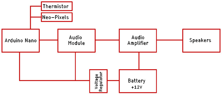
The block diagram of the Digital Firecracker is shown above. The brain of this project is an Arduino Nano. The Arduino nano controls the Audio module in which we have stored the sound files. Now the output of the audio module is connected to the input of an audio amplifier. The audio amplifier amplifies the low gain signal to a high amplitude signal which can drive a speaker. To power the circuit, we have a +12V battery pack with BMS. The 12V battery pack is connected to the Audio Amplifier Module because it needs 12V to operate. Finally, to power the Arduino and the Audio Module, we are using a 5V voltage regulator. This is how the basic circuitry works.
Components Required
The component required for this e-pataka is very generic and can be found in your local hobby store. There is only one component among them that you can find in any online store.
- PAM8610 Class-D audio Amplifier
- JQ6500 Voice Sound Module
- 7805 Voltage Regulator
- Arduino Pro mini
- Li-Po Battery
- WS2812B Neo Pixel LEDs
- Connecting Wires
Circuit Diagram of Arduino-Based Firecracker
The complete Circuit Diagram for the Arduino-based Green Firecracker is shown below.

The schematic for the Arduino-based fire crack is very simple as we have discussed in our block diagram, we have Arduino as the brain of our project and in the schematic diagram, the JQ6500 is the Audio module. We have connected the K1, K2, k3, and K4 pins of the Audio module to the four digital pins of the Arduino, and also connected the WS2812B with digital pin D2 of the Arduino. Finally, for the thermistor, we used the A1 pin of the Arduino to connect it.
The output of the Audio module which is the DAC_L, and DAC_R pin is connected to the audio amplifier module via a potentiometer, so we can adjust the output sound. Finally, we have the 7805-voltage regulator. On the input of the voltage regulator, we have a 12.6V battery pack connected, and the output is connected to the Arduino nano and the Audio module.
Arduino Code for Digital Firecracker
The code for the Arduino-based Digital Firecracker is very simple and easy to understand and requires only one library to work properly. The complete code for it is explained below.
We start off our code by including all the required libraries and as mentioned earlier, we need only the Adafruit_NeoPixel library and not much more. We start our code by defining all 4 pins of the audio module. And we also define the neopixel pin and the number of LEDs that are attached to it. Learn more about interfacing NeoPixels with Arduino here.
#include <Adafruit_NeoPixel.h>
#define PIN    6  // Digital IO pin connected to the NeoPixels.
#define NUMPIXELS 6  // Number of NeoPixels
#define  PIN_K1 9
#define  PIN_K2 8
#define  PIN_K3 7
#define  PIN_K4 6
Now we define the ADC pin in which the thermistor is connected and we declare the instance for the adafruit library.
#define THERMISTOR_PIN A1
Adafruit_NeoPixel pixels(NUMPIXELS, PIN, NEO_GRB + NEO_KHZ800);
Next, we have our setup function. In the setup function, we initialize the pins by defining all the pins as input and output. Next, we initialize the Serial and the neopixel instance.
void setup() {
  pinMode(THERMISTOR_PIN, INPUT);
  pinMode(PIN_K1, OUTPUT);
  pinMode(PIN_K2, OUTPUT);
  pinMode(PIN_K3, OUTPUT);
  pinMode(PIN_K4, OUTPUT);
  digitalWrite(PIN_K1, HIGH);
  digitalWrite(PIN_K2, HIGH);
  digitalWrite(PIN_K3, HIGH);
  digitalWrite(PIN_K4, HIGH);
  Serial.begin(115200);
  pixels.begin();
}
Next, we have our loop function, in the loop function we first read the analog pin and we clear the pixels by calling the clear() method of the neopixel library.
 int sensorValue = analogRead(THERMISTOR_PIN);
 // Serial.println(sensorValue);
  pixels.clear();
  pixels.show();
Next, we check if the value on the analog pin is less than 100 or not. If the value is less than 100, that means the temperature of the thermistor is greater than the ambient and we trigger a random() function, and depending on the output of the random() function we call our sound function() which is defined as bomb_sound_1 and bomb_sound_2
void loop() {
  int sensorValue = analogRead(THERMISTOR_PIN);
// Serial.println(sensorValue);
  pixels.clear();
  pixels.show();
  if (sensorValue < 100 ) {
    int rand_num = random(0, 3);
    Serial.println(rand_num);
    if (rand_num == 1) {
      bomb_sound_1();
      Serial.println("Triggred1 ");
    }
    if (rand_num == 2) {
      bomb_sound_2();
      Serial.println("Triggred2");
    }
  }
}
Next, we have three more functions named bomb_sound_1(), bomb_sound_2(), and flame() function, as the name implies these functions are there to animate flame as if a fuse is burning and in the end, it will produce a bright white light with a sound.
void bomb_sound_2() {
  digitalWrite(PIN_K2, LOW);
  for (int i = 0; i < NUMPIXELS; i++) {
    pixels.setPixelColor(i, pixels.Color(255, 0, 0));
    pixels.show();
    delay(750);
  }
  for (int i = 0; i < NUMPIXELS; i++) {
    pixels.setPixelColor(i, pixels.Color(255, 255, 255));
    pixels.show();
  }
  delay(1000);
  digitalWrite(PIN_K2, HIGH);
}
void flame() {
  int r = 226, g = 110, b = 35;
  for (int i = 0; i < pixels.numPixels(); i++) {
    int flicker = random(0, 55);
    int r1 = r - flicker;
    int g1 = g - flicker;
    int b1 = b - flicker;
    if (g1 < 0) g1 = 0;
    if (r1 < 0) r1 = 0;
    if (b1 < 0) b1 = 0;
    pixels.setPixelColor(i, r1, g1, b1);
  }
  pixels.show();
  delay(random(10, 113));
}
Testing E-Pataka
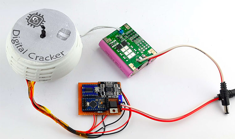
To test the Digital Cracker, we put everything on our table as you can see that in the image above. In the next step, we turned off our lights and lighted a flame in front of the thermistor
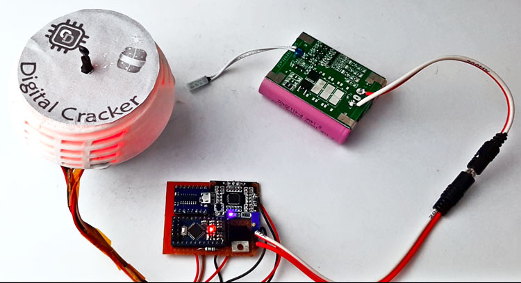
As you can see in the circuit the neo pixels light up and create a light effect. For better understanding do check out the video given below.
This is the end of this project and if you have any questions regarding this article, you can comment down below or you can ask in our forum.
Complete Project Code
#include <Adafruit_NeoPixel.h>
#define PIN    6  // Digital IO pin connected to the NeoPixels.
#define NUMPIXELS 6  // Number of NeoPixels
#define  PIN_K1 9
#define  PIN_K2 8
#define  PIN_K3 7
#define  PIN_K4 6
#define THERMISTOR_PIN A1
Adafruit_NeoPixel pixels(NUMPIXELS, PIN, NEO_GRB + NEO_KHZ800);
int interval = 15000;
unsigned long previousMillis = 0;
bool  flag = 0;
void setup() {
  pinMode(THERMISTOR_PIN, INPUT);
  pinMode(PIN_K1, OUTPUT);
  pinMode(PIN_K2, OUTPUT);
  pinMode(PIN_K3, OUTPUT);
  pinMode(PIN_K4, OUTPUT);
  digitalWrite(PIN_K1, HIGH);
  digitalWrite(PIN_K2, HIGH);
  digitalWrite(PIN_K3, HIGH);
  digitalWrite(PIN_K4, HIGH);
  Serial.begin(115200);
  pixels.begin();
}
void loop() {
  int sensorValue = analogRead(THERMISTOR_PIN);
  unsigned long currentMillis = millis();
  if ((unsigned long)(currentMillis - previousMillis) >= interval) {
    flag = 1;
    previousMillis = currentMillis;
  }
  Serial.println(sensorValue);
  pixels.clear();
  pixels.show();
  if (sensorValue < 130 && flag == 1)
  {
    flag = 0;
    int rand_num = random(0, 3);
    Serial.println(rand_num);
    if (rand_num == 1)
    {
      bomb_sound_1();
      Serial.println("Triggred1 ");

    }

    if (rand_num == 2)
    {
      bomb_sound_2();
      Serial.println("Triggred2");

    }
  }
}
void bomb_sound_1()
{
  digitalWrite(PIN_K1, LOW);

  for (int i = 0; i < 50; i++) {
    flame();
    delay(30);
  }
  for (int i = 0; i < NUMPIXELS; i++) {
    pixels.setPixelColor(i, pixels.Color(255, 255, 255));
    pixels.show();
  }
  delay(1000);
  digitalWrite(PIN_K1, HIGH);
}
void bomb_sound_2()
{
  digitalWrite(PIN_K2, LOW);
  for (int i = 0; i < NUMPIXELS; i++) {
    pixels.setPixelColor(i, pixels.Color(255, 0, 0));
    pixels.show();
    delay(750);
  }
  for (int i = 0; i < NUMPIXELS; i++) {
    pixels.setPixelColor(i, pixels.Color(255, 255, 255));
    pixels.show();
  }
  delay(1000);
  digitalWrite(PIN_K2, HIGH);
}
void flame()
{
  int r = 226, g = 110, b = 35;
  for (int i = 0; i < pixels.numPixels(); i++) {
    int flicker = random(0, 55);
    int r1 = r - flicker;
    int g1 = g - flicker;
    int b1 = b - flicker;
    if (g1 < 0) g1 = 0;
    if (r1 < 0) r1 = 0;
    if (b1 < 0) b1 = 0;
    pixels.setPixelColor(i, r1, g1, b1);
  }
  pixels.show();
  delay(random(10, 113));
}
This is nice