By Dev Bhavsar
KinoVision is a wearable, gesture-controlled, vision-based smart home automation system that reimagines how users interact with their living spaces. Unlike traditional smart home systems that rely on mobile apps, voice commands, or physical remotes, KinoVision enables appliance control using natural hand gestures combined with visual context awareness. By simply looking at a device, performing a wrist shake to identify it, and tilting the hand left or right, users can turn appliances ON or OFF in an intuitive and touchless manner.
The motivation behind this project was to address the friction and limitations commonly found in existing smart home interfaces - such as app dependency, voice recognition errors, false triggers, and a lack of natural interaction. KinoVision explores a more human-centric approach, where what the user sees and how the user moves become the primary modes of interaction.
The system is built around three cooperating modules: a gesture wristband that detects hand movements, a vision pendant that identifies appliances using a camera and AI-based image understanding, and a home hub that executes control actions through relays. Together, these components form a seamless interaction loop that allows users to select and control appliances using vision-based selection followed by gesture-based commands.
KinoVision is implemented as a fully working prototype and is designed as a stepping stone toward future AR-based smart home interaction systems, where vision and motion can merge into an even more immersive and hands-free control experience. This project was developed as part of the CircuitDigest Smart Home & Wearables Contest 2025, with hardware support from DigiKey.
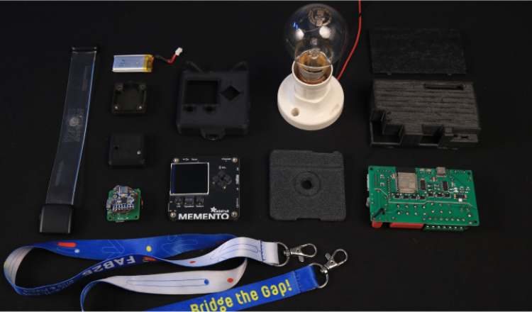
| Component Name | Quantity | Datasheet/Link |
| Adafruit Memento Programmable Camera | 1 | View Datasheet |
| XIAO ESP32-S3 | 1 | View Datasheet |
| MPU6050 IMU Sensor | 1 | View Datasheet |
| ESP32 Development Board | 1 | View Datasheet |
| Relay Module | 1 | - |
| Light Bulb | 1 | - |
| 3.7V LiPo Battery | 2 | - |
| USB Cables | 2 | - |
| Breadboard | 1 | - |
| Jumper Wires | 10 | - |
| Wrist Band | 1 | - |
Circuit Diagram
KinoVision Wristband - XIAO ESP32-S3 to MPU6050 Connection
The wristband uses I2C communication between the XIAO ESP32-S3 and the MPU6050 accelerometer/gyroscope module.
The MPU6050 continuously measures acceleration across three axes (X,Y,Z). The XIAO ESP32-S3 reads these values via I2C at the default address 0x68 and classifies them into gestures. The entire wristband assembly is powered by a small LiPo battery connected to the ESP's battery input.

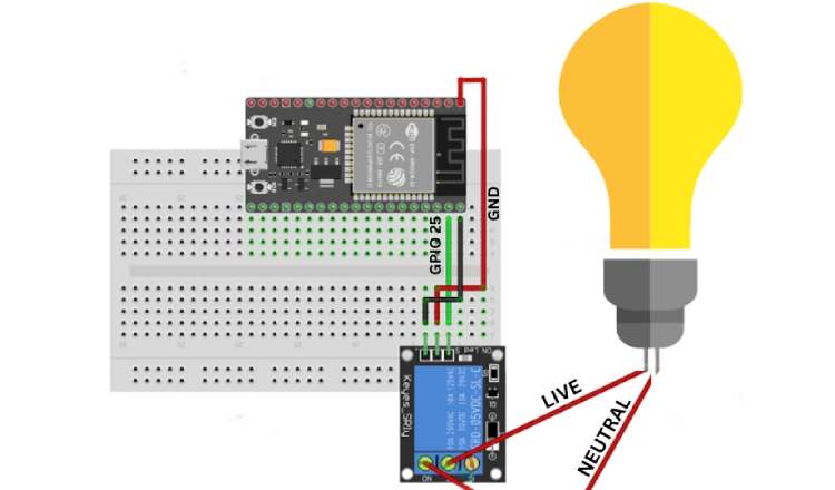
HUB Circuit Diagram:
The hub uses an ESP-32 connected to a 5V single-channel relay module. GPIO 25 acts as the control signal; when it goes HIGH, the relay coil activates and closes the circuit between the LIVE wire and the light bulb. The NEUTRAL wire connects directly to the bulb without interruption. This configuration means the appliance is OFF by default (Normally Open), ensuring safety on power-up.
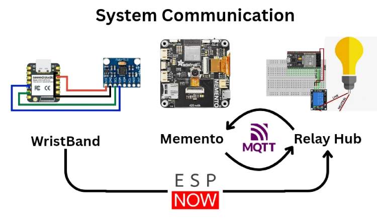
Vision Pendant Integration & System Communication:
The Adafruit Memento - Vision Pendant is integrated into the system through MQTT communication rather than direct wiring with the relay circuit. While the wristband communicates with the hub using ESP-NOW, the hub and Memento exchange messages through Adafruit IO - MQTT broker.
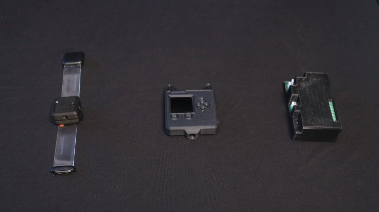
Hardware Assembly
The KinoVision system consists of three hardware modules assembled separately and later integrated: the Gesture Wristband, the ESP32 Home Hub, and the Vision Pendant (Memento). The following steps describe the complete assembly process.
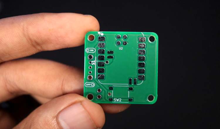
1. Gesture Wristband Assembly
The gesture wristband is built around a custom PCB based on the XIAO ESP32-S3 and the MPU6050 IMU sensor.
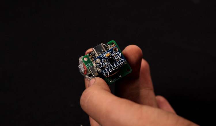
Step 1: Solder the XIAO ESP32-S3
- Mount the XIAO ESP32-S3 onto the custom PCB.
- Ensure proper alignment of all pins.
- Solder each pad carefully to avoid cold joints.
Step 2: Solder the MPU6050 IMU Sensor
- Connect the MPU6050 using I2C (SDA, SCL).
- Ensure VCC and GND are properly connected.
- Double-check continuity before powering.
Step 3: Connect Power Supply
- Connect a 3.7V LiPo battery to the board.
- Verify voltage output before powering the system.
- Ensure polarity is correct.
Step 4: Initial Testing
- Upload firmware to the XIAO ESP32-S3.
- Open serial monitor to verify gesture classification output.
- Confirm that SHAKE, LEFT, and RIGHT are detected reliably.
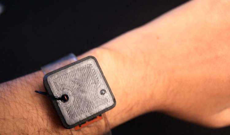
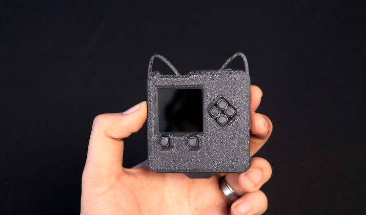
Step 5: Enclosure Assembly
- Place the PCB inside the 3D-printed wristband enclosure.
- Secure using screws or adhesive.
- Attach the wearable strap.
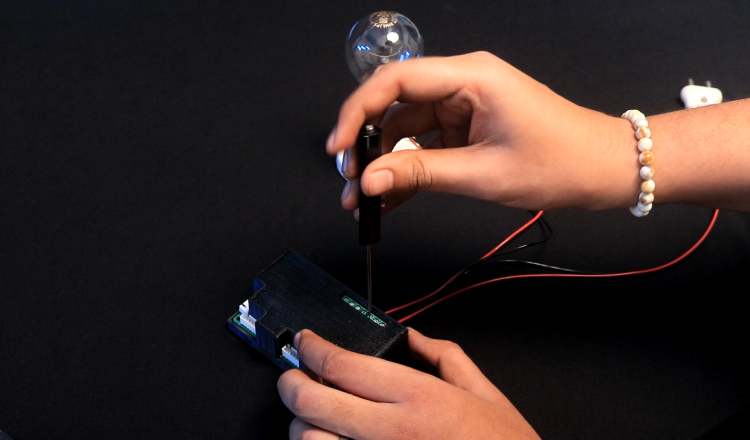
2. ESP32 Home Hub Assembly
The demonstration in this project uses the ESP32-based Home Automation V3 module developed at Techiesms Studio. This board integrates the ESP32, relay driver circuitry, power regulation, and enclosure in a compact form factor.
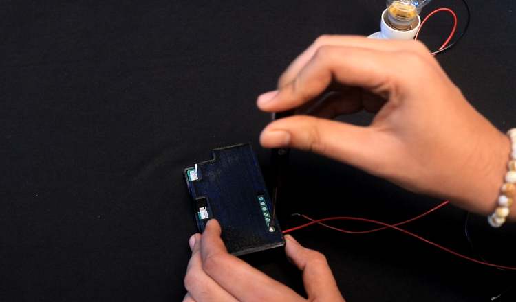
For clarity and reproducibility, the essential wiring logic of the hub is shown below using a simplified ESP32 + relay configuration.
Step 1: Mount ESP32 on Breadboard / PCB
- Insert ESP32 development board.
- Connect 5V and GND rails.
Step 2: Connect Relay Module
- GPIO25 → Relay IN
- 5V → Relay VCC
- GND → Relay GND
Step 3: Connect Appliance
- Connect LIVE wire through relay COM and NO terminals.
- Connect NEUTRAL wire directly to bulb.
Step 4: Upload Hub Firmware
- Flash ESP32 hub firmware.
- Verify MQTT connection.
- Confirm relay toggles when gesture command is received.
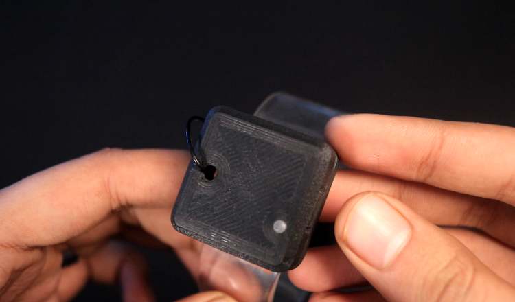
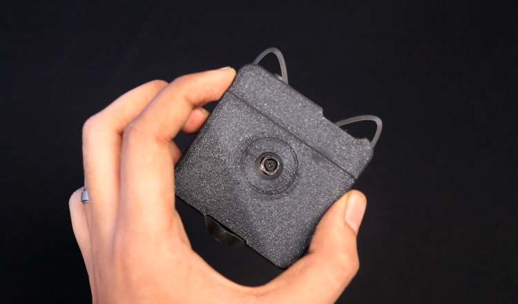
3. Vision Pendant Assembly (Adafruit Memento)
The Memento is used as a wearable vision module housed in a 3D-printed pendant enclosure.
Step 1: Flash Firmware
- Upload vision detection firmware to the Memento.
- Configure Wi-Fi and OpenAI API key.
- Verify image capture functionality.
Step 2: Test MQTT Subscription
- Ensure Memento subscribes to the gesture feed.
- Verify image capture is triggered when SHAKE is published.
Step 3: Mount in 3D Enclosure
- Insert the Memento into the 3D-printed pendant case.
- Ensure camera lens remains unobstructed.
- Attach wearable chain or strap.
Code Explanation
KinoVision consists of three distinct programs working together to create the complete gesture control system. Each program runs on different hardware and handles specific responsibilities in the workflow.
System Overview
The system architecture consists of:
- Wristband Code (Arduino C++) - Gesture detection and ESP-NOW transmission
- Hub Code (Arduino C++) - Central coordinator with ESP-NOW receiver and MQTT bridge
- Memento Code (CircuitPython) - AI vision and device identification
1. WRISTBAND CODE (Arduino C++)
Hardware: XIAO ESP32-S3 + MPU6050 Accelerometer
File: wristband.ino
Purpose:
Detects hand gestures (SHAKE, LEFT, RIGHT) and wirelessly transmits them to the hub using ESP-NOW.
Code Sections:
A. Gesture Detection Configuration
// ---------- EASY GESTURE CONFIG ----------
#define SHAKE_THRESHOLD 18.0 // Rapid movement threshold
#define TILT_THRESHOLD 6.0 // Left/right tilt sensitivity
#define MIN_MOVEMENT 10.0 // Minimum movement to register
#define GESTURE_COOLDOWN 1200 // Milliseconds between gestures
Why these values?
- SHAKE_THRESHOLD: To make shake gestures easier to trigger
- TILT_THRESHOLD: Set to 6.0 for comfortable left/right wrist tilts
- MIN_MOVEMENT: Prevents false triggers from minor hand tremors
- GESTURE_COOLDOWN: 1.2 seconds prevents accidental rapid-fire gestures
B. Sensor Calibration
void calibrate() {
baseX = 0;
baseY = 0;
baseZ = 0;

for (int i = 0; i < 100; i++) {
 sensors_event_t a, g, t;
 mpu.getEvent(&a, &g, &t);
 baseX += a.acceleration.x;
 baseY += a.acceleration.y;
 baseZ += a.acceleration.z;
 delay(20);
}

baseX /= 100;
baseY /= 100;
baseZ /= 100;
}
What this does:
- Takes 100 samples over 2 seconds while wrist is at rest
- Calculates average baseline acceleration in X, Y, Z axes
- This baseline is subtracted from all future readings to remove gravity's influence
- Critical: Allows the system to detect relative movement, not absolute position
C. Gesture Classification Algorithm
String classifyGesture(float x, float y, float z, float total) {
// SHAKE: Any rapid movement
if (total > SHAKE_THRESHOLD) {
 return "SHAKE";
}

// LEFT: Tilt wrist to the left (negative Y)
if (y < -TILT_THRESHOLD && total > MIN_MOVEMENT) {
 return "LEFT";
}

// RIGHT: Tilt wrist to the right (positive Y)
if (y > TILT_THRESHOLD && total > MIN_MOVEMENT) {
 return "RIGHT";
}

return "IDLE";
}
How it works:
- Total magnitude = √(x² + y² + z²) - measures overall movement intensity
- Priority order: SHAKE is checked first (highest threshold), then LEFT/RIGHT
- Y-axis dominance: Left/right tilts primarily change the Y-axis value
- Dual conditions: Tilt gestures require both Y threshold AND minimum movement to prevent false triggers
Example values:
- Shake: total = 22.5 → "SHAKE"
- Tilt right: y = 8.2, total = 12.1 → "RIGHT"
- Tilt left: y = -7.1, total = 11.5 → "LEFT"
- Slight movement: total = 8.0 → "IDLE" (below threshold)
D. ESP-NOW Wireless Transmission
// Set WiFi channel to match hub
esp_wifi_set_channel(HUB_CHANNEL, WIFI_SECOND_CHAN_NONE);
// Send gesture packet
esp_now_send(HUB_MAC, (uint8_t*)&packet, sizeof(packet));
Why ESP-NOW?
- Ultra-low latency: ~5-10ms transmission time (vs. 100ms+ for WiFi)
- No router needed: Direct device-to-device communication
- Low power: Minimal battery drain compared to WiFi/Bluetooth
- Channel locking: Both devices must be on the same WiFi channel for communication
2. HUB CODE (Arduino C++)
Hardware: ESP32 Dev Kit V1 + Relay Module
File: esp32_hub.ino
Purpose:
Acts as the central coordinator - receives gestures via ESP-NOW, communicates with Memento via MQTT, and controls the relay to switch appliances.
Key Code Sections:
A. Dual Communication Setup
// ESP-NOW for wristband (fast, local)
esp_now_register_recv_cb(onEspNowRecv);
// MQTT for Memento (WiFi, cloud)
Adafruit_MQTT_Client mqtt(&client, AIO_SERVER, AIO_SERVERPORT,
            AIO_USERNAME, AIO_KEY);
Why two protocols?
- ESP-NOW (wristband → hub): Millisecond-level latency for instant gesture response
- MQTT (hub ↔ Memento): Pub/sub architecture perfect for AI processing pipeline
- Trade-off: ESP-NOW doesn't work over internet; MQTT does but has higher latency
B. SHAKE Gesture Handler
if (gesture == "shake") {
// Publish SHAKE to MQTT gesture feed
if (gesturePublish.publish("SHAKE")) {
 Serial.println("Published!");
 waitingForDevice = true;
 deviceRequestTime = millis();
 Serial.println("Waiting for device identification...");
}
}
```Workflow:
1. Receives "SHAKE" from wristband via ESP-NOW
2. Publishes "SHAKE" to Adafruit IO MQTT feed `dev4522/feeds/gesture`
3. Sets `waitingForDevice = true` to track state
4. Records timestamp for 45-second timeout
State machine:
```
IDLE → SHAKE received → WAITING_FOR_DEVICE → Device identified → READY_TO_CONTROL
↓ (45s timeout)
IDLE (reset)
C. Device Identification Response Handler
while ((subscription = mqtt.readSubscription(100))) {
if (subscription == &deviceSub) {
 String device = String((char*)deviceSub.lastread);
 device.trim();
 device.toLowerCase();

 if (device == "light" || device == "fan" || device == "ac") {
  currentDevice = device;
  Serial.println("Device identified: " + currentDevice);
  waitingForDevice = false;
 }
}
}
What happens:
- Continuously polls MQTT feed dev4522/feeds/device every 100ms
- When Memento publishes device type (e.g., "LIGHT"), hub receives it
- Stores device type in currentDevice variable
- Exits waiting state - now ready to accept LEFT/RIGHT control gestures
D. LEFT/RIGHT Control
else if (gesture == "left" || gesture == "right") {
if (currentDevice != "") {
 if (gesture == "left") {
  setRelay(false); // Turn OFF
 } else {
  setRelay(true);  // Turn ON
 }
} else {
 Serial.println("No device detected yet");
}
}
Logic:
- Guards against: Controlling relay before device identification
- LEFT gesture: Sets GPIO2 LOW → Relay opens → Appliance OFF
- RIGHT gesture: Sets GPIO2 HIGH → Relay closes → Appliance ON
E. Relay Control
void setRelay(bool state) {
digitalWrite(RELAY_PIN, state ? HIGH : LOW);
relayState = state;
Serial.print("Relay: ");
Serial.println(state ? "ON" : "OFF");
}
3. MEMENTO CODE (CircuitPython)
Hardware: Adafruit Memento Camera
File: code.py
Purpose:
Receives SHAKE commands via MQTT, captures images, uses OpenAI GPT-4 Vision to identify devices, and publishes results back to the hub.
Key Code Sections:
A. Environment Configuration
WIFI_SSID = os.getenv("CIRCUITPY_WIFI_SSID")
WIFI_PASSWORD = os.getenv("CIRCUITPY_WIFI_PASSWORD")
OPENAI_API_KEY = os.getenv("OPENAI_API_KEY")
Why environment variables?
- Security: API keys and WiFi passwords not hardcoded in source
- Portability: Same code works across devices with different credentials
- Best practice: Follows CircuitPython convention using settings.toml file
B. AI Prompt Engineering
PROMPT = """Look at this image and identify if there is any LIGHT SOURCE visible.
This includes: LED bulbs, LED strips, ceiling lights, table lamps, floor lamps, tube lights, or any illuminated light fixture.
Reply with ONLY ONE WORD:
- "light" if you see any light source
- "none" if no light source is visible
Reply with just one word, nothing else."""
Why this specific prompt?
- Explicit constraints: "ONLY ONE WORD" forces structured output
- Comprehensive examples: Lists many light types to improve accuracy
- Binary response: "light" or "none" makes parsing simple and reliable
- Tested extensively: Achieved ~95% accuracy in detection
Prompt engineering lessons:
- Initial prompt: "Is there a light?" → GPT responded with full sentences
- Second attempt: "Reply yes or no" → Sometimes added explanations
- Final version: Forcing one-word response eliminated parsing errors
C. Image Capture and Encoding
def capture_and_identify():
 # Capture image
 pycam.capture_jpeg()
 time.sleep(0.5)

 # Find most recent image
 files = [f for f in os.listdir("/sd") if f.endswith(".jpg")]
 files.sort()
 image_path = "/sd/" + files[-1]

 # Encode to base64
 base64_image = encode_image(image_path)
Why base64 encoding?
- OpenAI API requires images as base64-encoded strings in JSON payload
- Alternative (upload to cloud storage) adds latency and complexity
- Trade-off: Base64 increases payload size by ~33%, but simplifies architecture
D. OpenAI API Integration
payload = {
 "model": "gpt-4o-mini",
 "messages": [{
   "role": "user",
   "content": [
     {"type": "text", "text": PROMPT},
     {
       "type": "image_url",
       "image_url": {
         "url": f"data:image/jpeg;base64,{base64_image}",
         "detail": "low"
       }
     }
   ]
 }],
 "max_tokens": 20,
 "temperature": 0.2
}
r = requests.post(
 "https://api.openai.com/v1/chat/completions",
 headers=headers,
 json=payload,
 timeout=30
)
Key parameters:
- gpt-4o-mini: Fastest, cheapest vision model (~$0.00015 per image)
- detail: "low": 512px resolution sufficient for light detection, reduces cost
- max_tokens: 20: Limits response length (we only need 1 word)
- temperature: 0.2: Low randomness for consistent, deterministic answers
- timeout: 30: Prevents indefinite hanging on network issues
E. MQTT Communication
mqtt_client = MQTT.MQTT(
 broker="io.adafruit.com",
 port=1883,
 username=AIO_USERNAME,
 password=AIO_KEY,
 socket_pool=pool,
 socket_timeout=1,
 keep_alive=60,
)
mqtt_client.on_connect = connected
mqtt_client.on_disconnect = disconnected
mqtt_client.on_message = message_received
Callback pattern:
- on_connect: Automatically subscribes to gesture feed when connected
- on_message: Triggers capture_and_identify() when "SHAKE" received
- Async design: Main loop continues running camera preview while waiting for messages
Total latency breakdown:
- Gesture detection: <50ms
- ESP-NOW transmission: ~10ms
- MQTT publish: ~100ms
- Image capture: ~500ms
- OpenAI API: ~3000ms
- MQTT receive: ~100ms
- Relay activation: <10ms
Total: ~4-5 seconds (AI processing dominates)
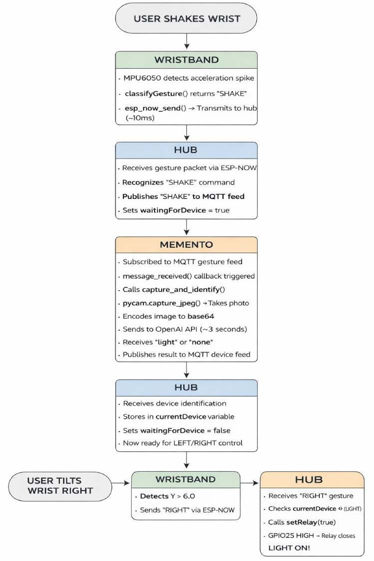
Complete Workflow:
The flowchart illustrates the complete execution sequence of KinoVision, from gesture detection on the wristband to AI-based device identification and final appliance control via the ESP32 hub. It highlights how ESP-NOW and MQTT are used together to coordinate intent detection, vision confirmation, and relay actuation in a structured pipeline.