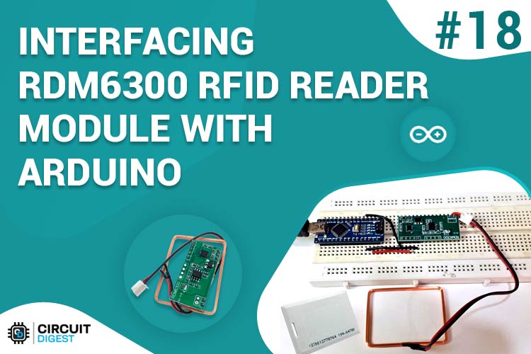
RFID (short for Radio Frequency Identification) tagging is an ID system that uses electromagnetic waves in radio frequency to transfer data. A simple RFID system consists of just two components: the tag itself and a read/write device. The read/write device consists of a Radio Frequency module and an antenna that generates a high-frequency electromagnetic field while the tag is usually a passive device that contains a microchip that stores and processes information. Previously we interfaced MFRC522 RFID Module and EM-18 RFID Reader with Arduino.
In this tutorial, we are going to interface RDM6300 RFID Reader Module with Arduino Nano. The RDM6300 RFID Reader is one type of RFID module with a 125 kHz frequency. This RFID module can read data from 125 kHz compatible read-only tags and read/write 125 kHz cards.
Components Required for Interfacing RDM6300 with Arduino
- Arduino Nano
- RDM6300 RFID Reader Module
- 125 kHz Tags
- Jumper Wires
- Breadboard
RDM6300 RFID Reader Module
The RDM6300 125 kHz EM4100 RFID Card ID Reader Module is designed to read and write data from 125 kHz compatible tags. It can be used in surveillance systems for workplaces and residences, personal authentication, access management, anti-forgery, digital toys, and output control systems, among other items. RDM6300 Series non-contact RFID board uses an advanced RF receiver circuit and built-in MCU architecture, combined with a high-efficiency decoding algorithm, to read the EM4100 and all the compatible cards. It uses serial TTL at a 9600 baud rate to transmit the RFID tag data. Any microcontroller with UART serial peripheral can be used to work with this RFID reader.

RDM6300 RFID Reader Module Pinout
|
Pin Name |
Pin Description |
|
5V |
Power Supply Pin |
|
GND |
Ground |
|
RX |
Data Receive pin |
|
TX |
Data Transmit pin |
|
ANT1 |
Antenna connection pin |
|
ANT2 |
Antenna connection pin |
RDM6300 RFID Reader Module Specifications:
- Operating Frequency: 125KHZ
- Baud Rate: 9600
- Interface: TTL level RS232 format
- Working voltage: DC 5V
- Working current: <50mA
- Receive distance: 20~50mm
- Dimension (mm): 38.5 x 20
- Weight: 7g
The RDM6300 RFID module is similar to the EM-18 RFID reader module. Both the modules have the same operating frequency i.e. 125 KHz and support Serial RS232/TTL output while the operating frequency for RC522 is 13.56 kHz.
Circuit Diagram for Interfacing RDM6300 with Arduino
The schematic for Interfacing RDM6300 RFID Reader Module with Arduino is given below:
Wire up the Arduino to the RDM6300 RFID Reader Module as shown in the diagram. The 5V and GND pin of the RDM6300 module is connected to the 5V and GND pin of Arduino Nano while the TX pin of the module is connected to D6 of Nano. The RX pin is not required as we do not send data to the RFID module in this tutorial. Lastly, connect the antenna to ANT1 and ANT2 pin in any polarity.

Programming Arduino for RDM6300 RFID Reader
The code for RFID card reader using Arduino Nano and RDM6300 is very simple. Here we used the rdm6300 library to read the data. The complete code is given at the end of the document. An explanation of the code is as follows:
Start the code by including the RDM6300 RFID Reader library.
#include <rdm6300.h>
Then define all the necessary pins that are required to read the sensor data and control the LED.
#define RDM6300_RX_PIN 6
Then inside the setup() function, initialize the serial monitor at 9600 for debugging purposes. Also, initialize the RFID Reader Module.
void setup()
{
  Serial.begin(9600);
  rdm6300.begin(RDM6300_RX_PIN);
  Serial.println("\nPlace RFID tag near the rdm6300...");
}
Then inside the loop() function, check if the tag is near, if yes, then read the tag number and print it on Serial Monitor.
void loop()
{
  if (rdm6300.update())
    Serial.println(rdm6300.get_tag_id(), HEX);
  delay(10);
}
Testing the RDM6300 RFID Reader
Once your code and hardware are ready, connect Arduino to the laptop and upload the code. After that, open the serial monitor at a baud rate of 9600, and scan the RFID tag on the Module’s Antenna. Tag number will be printed on the serial monitor.

This is how you can interface RDM6300 RFID Reader with Arduino. The complete working of the project can be found in the video given below; if you have any questions, feel free to write them in the comment section below.
Complete Project Code
#include <rdm6300.h>

#define RDM6300_RX_PIN 2

#define READ_LED_PIN 13

Rdm6300 rdm6300;

void setup()

{

  Serial.begin(9600);

  pinMode(READ_LED_PIN, OUTPUT);

  digitalWrite(READ_LED_PIN, LOW);

  rdm6300.begin(RDM6300_RX_PIN);

  Serial.println("\nPlace RFID tag near the rdm6300...");

}

void loop()

{

  /* if non-zero tag_id, update() returns true- a new tag is near! */

  if (rdm6300.update())

    Serial.println(rdm6300.get_tag_id(), HEX);

  digitalWrite(READ_LED_PIN, rdm6300.is_tag_near());

  delay(10);

}


