
In one of our basic projects, we have shown you how you can interface a MAX30102 Pulse Oximeter and Heart Rates Sensor With Arduino, but one of the major problems with that sensor is its inconsistency, and lack of support for Arduino IDE which is why in this article we thought to use a simple pulse sensor to measure the heartbeat. This pulse sensor is a well-designed plug-and-play heart rate sensor for Arduino. This sensor is easy to use and has many applications that is why it is a perfect choice for students, artists, athletes, manufacturers, and game & mobile developers who want to incorporate live heart-rate data into their projects.
Pulse Sensor Pinout
The pulse sensor comes with a flat ribbon cable with three male header connectors. The Pinout of the Pulse sensor is given below:

S(Signal) is the Analog output pin of the Sensor Module that will give us an analog reading directly from the sensor.
VCC is the supply pin of the Sensor. Connect it to the 5V pin of the Arduino.
GND is the Ground pin of the Sensor. Connect it to the Ground pin of the Arduino.
How Does a Pulse Sensor Module Work?
The fundamental working of the optical pulse sensor is very simple and easy to understand. An optical pulse sensor shines a green light with 550 nm wavelength through the skin and measures the reflected light; this method of pulse detection is called Photoplethysmogram. The working of the Pulse Sensor is given below.

The pulse sensor shines light through the skin and measures the reflection with the photodetector. This method of pulse detection through light is called Photoplethysmogram. The working of the sensor can be divided into two parts, one is heart rate measurement and another is blood oxygen level measurement.
The oxygen in the haemoglobin has a specific characteristic, that is it can absorb a certain amount of green light. The more oxygen in the blood, the blood becomes redder that increases the light absorption rate, and reduces the reflection. As the blood is pumped through the veins in the finger the amount of reflected light changes creating an oscillating waveform. And by measuring this wave we can get the heartbeat reading. The amplitude of the signal coming out of the sensor is very small and noisy that is why the signal is passed through with a Low pass filter and then it gets amplified by the opamp that is read by the Arduino.
Pulse Sensor Module – Parts
This is a low-power, low-cost, rugged sensor that can be used for many different applications which makes it popular for many different applications where heart rate measurement becomes necessary.
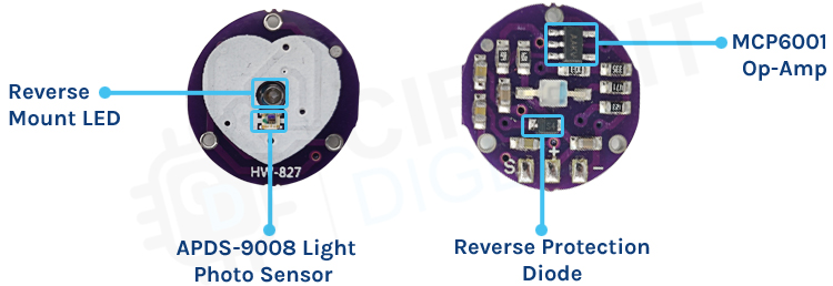
If you look in the front of the sensor, you can see only the LED and the photodiode itself. But the real circuit is in the backside of the sensor. The low power high bandwidth op-amp in the circuit is configured to provide some gain to the circuit and we have a reverse voltage protection diode to protect the circuit from ESD and reverse voltage. Other capacitors and resistors in the PCB are used for the RC filter that reduces any external noise in the circuit.
Commonly Asked Questions about Pulse Sensor Module
Can you tell blood pressure from a pulse?
The pulse will give the basic information required to estimate the systolic blood pressure (the upper number of blood pressure readings). Keep in mind, that this is a very rough estimate and only indicates if the systolic blood pressure is not low. Blood pressure monitoring should be done with a cuff and a stethoscope.
What is systolic and diastolic in blood pressure measurement?
Blood pressure is measured using two numbers: The first number, called systolic blood pressure, measures the pressure in your arteries when your heart beats. The second number, called diastolic blood pressure, measures the pressure in your arteries when your heart rests between beats.
What is neural control of blood pressure?
Neurological regulation of blood pressure and flow depends on the cardiovascular centers located in the medulla oblongata. This cluster of neurons responds to changes in blood pressure as well as blood concentrations of oxygen, carbon dioxide, and other factors such as pH.
What is an HRM sensor?
Heart rate monitor (HRM) is a personal monitoring device that allows one to measure/display heart rate in real-time or record the heart rate for later study. It is largely used to gather heart rate data while performing various types of physical exercise
Circuit Diagram for Pulse Sensor Module
The circuit diagram of the Pulse sensor module is shown below. The first important part of this circuit is the 10uF filter capacitor followed by the Green LED and a 470R resistor.

The 470R resistor is the current limiting resistor for the sensor module. Also in the circuit, you can see that the circuit is powered through a diode. The diode serves two purposes: first it acts as reverse polarity protection and second it protects the circuit from transients. After the diode, the power is distributed between the MCP6001 op-amp and the APDS-9008 photodiode sensor IC. The output amplitude of the sensor IC is very low and noisy. That is why we need to filter it through a set of RC low pass filters then the cleaned signal gets amplified by the op-amp and we can process the data with a microcontroller.
Arduino Pulse Sensor – Connection Diagram
Now that we completely understand how the pulse sensor works; we can connect all the required wires to the Arduino UNO board, and in this section of the article, we will discuss just that!

Arduino pulse sensor circuit diagram is is shown in the above figure. We are using the A0 pin of the Arduino to process the data out of the sensor. And the power pins of the sensor are connected to the 5V and Ground pins of the Arduino. The practical test hardware is shown below.

Arduino Code for Interfacing Pulse Sensor Module with Arduino
The Arduino pulse sensor code is simple and easy to understand, and most of the hard part is handled by the PulseSensorPlayground.h library, speaking of the library this is not a standard library of the Arduino and needs to be installed separately with the library manager. To do that, just search for pulsesensor in the library manager window and install the PulseSensor Playground by Joel Murphy, Yury Gitman. Once this is installed and everything is ready, we can move on to the next part of the code.

As we have said earlier, the code portion for this project will be very simple, that is why we have used a simple example code from the library to manage all the heavy lifting for us. But let's not get lazy and see how the code works.
We start our code by including all the required libraries and variables that is required to process the data out of the sensor.
#define USE_ARDUINO_INTERRUPTS true    // Set-up low-level interrupts for most acurate BPM maths.
#include <PulseSensorPlayground.h>     // Includes the PulseSensorPlayground Library.
//  Variables
const int PulseWire = 0;       // PulseSensor PURPLE WIRE connected to ANALOG PIN 0
const int LED13 = 13;          // The on-board Arduino LED, close to PIN 13.
int Threshold = 550;           // Determine which Signal to "count as a beat" and which to ignore.
                               // Use the "Getting Started Project" to fine-tune Threshold Value beyond default setting.
                               // Other
Next, we create an instance of the PulseSensorPlayground object called "pulseSensor" with this instance we will be able to access all the methods of the class.
PulseSensorPlayground pulseSensor; // Creates an instance of the PulseSensorPlayground object called "pulseSensor
Next, we have our setup function. In the setup function, we initialize the serial for debugging.
Next we configure the PulseSensor object, by assigning our variables to it. Next, we pass on the LED13 variable to pulseSensor.blinkOnPulse function that will blink the LED with heartbeat. Then we set the threshold for the sensor with the help of pulseSensor.setThreshold variable. Finally we created a pulseSensor Object and ended our setup function.
void setup() {
  Serial.begin(9600);          // For Serial Monitor
  // Configure the PulseSensor object, by assigning our variables to it.
  pulseSensor.analogInput(PulseWire);
  pulseSensor.blinkOnPulse(LED13);       //auto-magically blink Arduino's LED with heartbeat.
  pulseSensor.setThreshold(Threshold);
  // Double-check the "pulseSensor" object was created and "began" seeing a signal.
   if (pulseSensor.begin()) {
    Serial.println("We created a pulseSensor Object !");  //This prints one time at Arduino power-up,  or on Arduino reset.
  }
}
Next we have our loop function. In the loop function, we call the function on our pulseSensor object that returns BPM as an integer that we hold on to the myBPM variable. Now we continuously check if a beat happened or not. If so, we print the result in the serial monitor window.
void loop() {
 int myBPM = pulseSensor.getBeatsPerMinute();  // Calls function on our pulseSensor object that returns BPM as an "int".
                                               // "myBPM" hold this BPM value now.
if (pulseSensor.sawStartOfBeat()) {            // Constantly test to see if "a beat happened".
 Serial.println("♥  A HeartBeat Happened ! "); // If test is "true", print a message "a heartbeat happened".
 Serial.print("BPM: ");                        // Print phrase "BPM: "
 Serial.println(myBPM);                        // Print the value inside of myBPM.
}
  delay(20);                    // considered best practice in a simple sketch
}
This marks the end of our code portion and we can move on to the next section of the article.
Working of the Pulse Sensor Module
The gif below shows the practical circuit of Pulse Sensor with Arduino. You can see on the left-hand side of the window we have our Arduino to which we have hooked up our pulse sensor. The sensor is attached to my finger with a piece of tape, and on the right side of the window, you can see the serial monitor window in which you can see the live heart rate measured by the sensor.
Error in Reading Pulse Sensor?- Here is what you Should do
- If you are having trouble reading the pulse sensor, then please first check the operating voltage of the device. The stable operating voltage of this device is 3.3V to 5.5V. Driving the sensor with any other voltage values will make the sensor unstable.
- If you are having fluctuations in the reading try taping the sensor with your finger this will keep result in constant blood flow and that in the end stabilises the result.
- Most importantly this sensor takes a lot of time before it produces stable output. So you need to be patient before you get a stable result.
Projects using Arduino and Pulse Sensor Module

If you are interested in learning PIC Microcontrollers and its working, this project can be what you are looking for, because in this project we have use a PIC microcontroller and a generic Pulse Sensor to build a heart rate monitoring system, that uses the ADC on the PIC microcontroller to process the data.

If you are searching some IoT project Ideas then this project could be for you, because in this project we have used one of our favourite microcontroller Arduino and a Pulse Sensor to build a Heart Beat Monitoring System that is able to send the data to a thingspeak server instantaneously.

If you are looking for some simple IoT related project on the internet, this project can be an interesting one for you because in this project we have used a NodeMCU microcontroller and a Pulse Sensor to build a Painter Monitoring System that can come in handy in emergency situations.
Supporting Files


Complete Project Code
/*  Getting_BPM_to_Monitor prints the BPM to the Serial Monitor, using the least lines of code and PulseSensor Library.
 *  Tutorial Webpage: https://pulsesensor.com/pages/getting-advanced
 *
--------Use This Sketch To------------------------------------------
1) Displays user's live and changing BPM, Beats Per Minute, in Arduino's native Serial Monitor.
2) Print: "♥  A HeartBeat Happened !" when a beat is detected, live.
2) Learn about using a PulseSensor Library "Object".
4) Blinks LED on PIN 13 with user's Heartbeat.
--------------------------------------------------------------------*/
#define USE_ARDUINO_INTERRUPTS true    // Set-up low-level interrupts for most acurate BPM math.
#include <PulseSensorPlayground.h>     // Includes the PulseSensorPlayground Library.
//  Variables
const int PulseWire = 0;       // PulseSensor PURPLE WIRE connected to ANALOG PIN 0
const int LED13 = 13;          // The on-board Arduino LED, close to PIN 13.
int Threshold = 550;           // Determine which Signal to "count as a beat" and which to ignore.
                               // Use the "Gettting Started Project" to fine-tune Threshold Value beyond default setting.
                               // Otherwise leave the default "550" value.
PulseSensorPlayground pulseSensor;  // Creates an instance of the PulseSensorPlayground object called "pulseSensor"
void setup() {
  Serial.begin(9600);          // For Serial Monitor
  // Configure the PulseSensor object, by assigning our variables to it.
  pulseSensor.analogInput(PulseWire);
  pulseSensor.blinkOnPulse(LED13);       //auto-magically blink Arduino's LED with heartbeat.
  pulseSensor.setThreshold(Threshold);
  // Double-check the "pulseSensor" object was created and "began" seeing a signal.
   if (pulseSensor.begin()) {
    Serial.println("We created a pulseSensor Object !");  //This prints one time at Arduino power-up,  or on Arduino reset.
  }
}
void loop() {
 int myBPM = pulseSensor.getBeatsPerMinute();  // Calls function on our pulseSensor object that returns BPM as an "int".
                                               // "myBPM" hold this BPM value now.
if (pulseSensor.sawStartOfBeat()) {            // Constantly test to see if "a beat happened".
 Serial.println("♥  A HeartBeat Happened ! "); // If test is "true", print a message "a heartbeat happened".
 Serial.print("BPM: ");                        // Print phrase "BPM: "
 Serial.println(myBPM);                        // Print the value inside of myBPM.
}
  delay(20);                    // considered best practice in a simple sketch.
}
