
By Moksha Kumbhaj
Gesture Link is an assistive technology system designed to improve communication and independence for differently-abled individuals. The project combines two main modules: Visora (AI-powered smart glasses) and Gestura (bilateral assistive gloves)
The goal of this project is simple but powerful: to reduce communication barriers between visually impaired and speech-impaired individuals. Many existing assistive devices are expensive, limited in functionality, or dependent on internet connectivity. Gesture Link solves this by offering a fully offline, real-time, wearable solution that is affordable and practical.
Visora helps visually impaired users detect objects, recognize colors, and navigate safely using computer vision, audio feedback, and haptic alerts. Gestura consists of two smart gloves - one that converts hand gestures into speech and another that converts speech into tactile Braille vibrations. Together, they enable two-way communication between users through gesture, speech, and touch.
This project was developed with the intention of creating an inclusive, portable, and user-friendly system that empowers differently-abled individuals to communicate more independently and confidently.
GESTURA : GLOVE - A
GESTURA : GLOVE - B
Components Required
| Component Name | Quantity | Datasheet/Link |
| Seeed Studio ESP32 S3 Sense | 1 | - |
| Seeed Studio ESP32 C6 | 1 | - |
| 1.8 inch TFT Display | 1 | - |
| DHT11 | 2 | - |
| MAX98357A | 1 | - |
| DF Player Mini | 1 | - |
| Oled Display 1.3 inch | 1 | - |
| Oled Display 0.96 inch | 1 | - |
| ESP32 Dev Module | 1 | - |
| I2S Microphone | 1 | - |
| 6 Axis MPU | 1 | - |
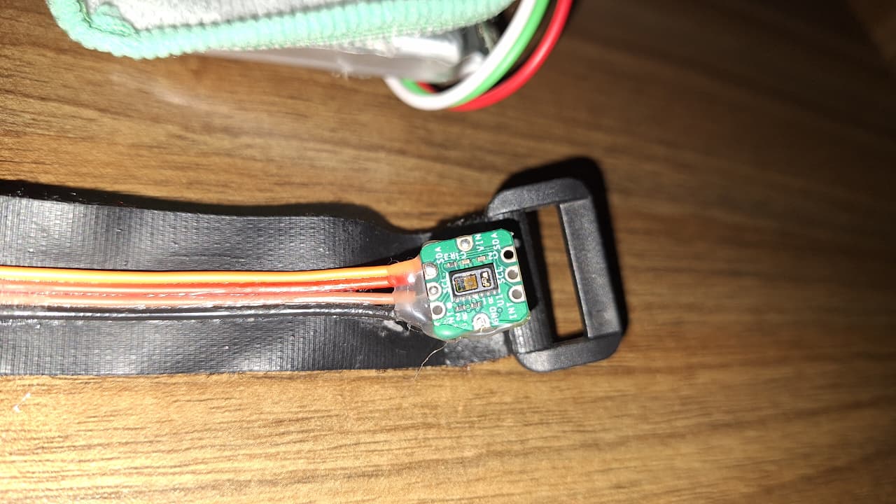
| MAXREFDES117 Bio-Sensor from Analog Devices | 1 | View Datasheet |
| Push To On Button | 3 | - |
| Flex Sensor | 4 | - |
| Speaker | 2 | - |
| Vibration Motor | 12 | - |
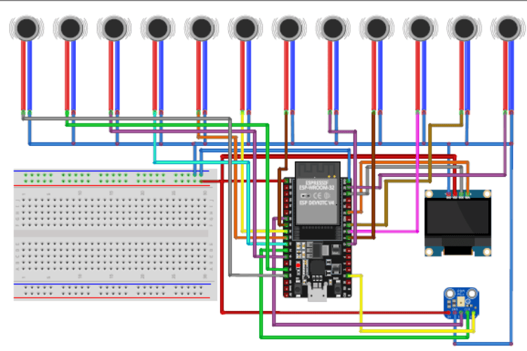
Circuit Diagram
GLOVE-A Circuit Diagram

GLOVE-B Circuit Diagram
VISORA Module Circuit Diagram
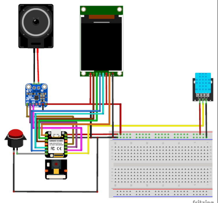
The complete circuit diagrams of all modules used in the system are attached below. These diagrams show detailed component connections, pin configurations, and power distribution for each unit.
Each diagram clearly represents:
- Microcontroller pin connections
- Sensor wiring
- Power supply lines
- Communication interfaces
Hardware Assembly
The Gesture Link system is built using dedicated hardware for each module to ensure reliability, offline processing, and real-time response. The system consists of Visora (Smart Glasses), Glove A (Gesture-to-Speech), and Glove B (Speech-to-Braille)
Below is the updated hardware configuration based on the final components used.
A. Visora – Smart Glasses
Main Controller
- ESP32-S3 Sense (Seeed Studio)
This board handles camera processing, display control, audio output, and sensor data.
Display
- 1.8” ST7735 TFT Display
- Used to display system status, environmental data, and visual feedback. Connected via SPI interface.
Audio System
- MAX98357A Audio Amplifier Module
- Used for clear audio output.
- Speaker connected to the amplifier.
Sensors
- DHT11 – Measures temperature and humidity.
- MAXREFDES117 Bio-Sensor (Analog Devices) – Used for heart rate and SpO₂ monitoring. This ensures health monitoring while using the glasses.
Assembly Steps
- Mount ESP32-S3 Sense securely on the frame housing.
- Fix the ST7735 TFT on the front/side area for clear visibility.
- Connect TFT via SPI (SCK, MOSI, CS, DC, RST).
- Connect MAX98357A via I2S pins from ESP32-S3.
- Attach speaker near the ear section.
- Connect DHT11 to a digital GPIO pin.
- Connect MAXREFDES117 via I2C (SDA, SCL).
- Secure battery and ensure proper voltage regulation.
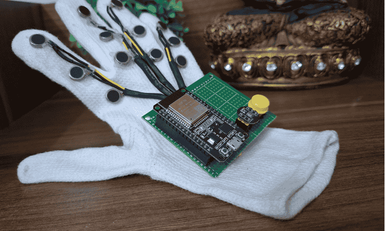
B. Glove A – Gesture-to-Speech
Main Controller
- ESP32-C6 (Seeed Studio Board)
Chosen for compact size and wireless capability.
Gesture Sensors
- 4 Flex Sensors – Attached along fingers for bend detection.
- MPU (Motion Processing Unit / IMU) – Detects hand orientation and motion.
Audio Output
- DFPlayer Mini
- Small Ω speaker connected to DFPlayer.
Environmental & Health Monitoring
- DHT11 – Measures temperature.
- MAXREFDES117 Bio-Sensor (Analog Devices) – Measures heart rate and SpO₂.
Assembly Steps
- Stitch 4 flex sensors along index, middle, ring, and little finger.
- Mount MPU on the back of the hand.
- Mount ESP32-C6 near the wrist.
- Connect flex sensors to analog GPIO pins.
- Connect MPU via I2C.
- Connect DFPlayer Mini via UART.
- Attach speaker near wrist section.
- Connect DHT11 to digital pin.
- Connect MAXREFDES117 via I2C bus.
- Secure battery and insulate all connections.
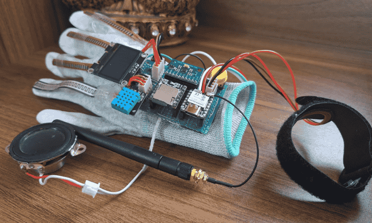
C. Glove B – Speech-to-Braille
This glove is critical for tactile communication and relies heavily on vibration feedback and bio-monitoring.
Main Controller
- ESP32 Dev Board
Tactile Output
- 12 Vibration Motors
- Arranged in a Braille pattern layout to represent characters through tactile feedback.
User Controls
- Push Button – Used for mode switching or confirmation input.
Health Monitoring
- MAXREFDES117 Bio-Sensor (Analog Devices)
- Important in this module to monitor user vitals during prolonged tactile communication.
Display
- OLED Display – Used for system status and debugging.
Assembly Steps
- Arrange 12 vibration motors in a Braille matrix layout.
- Fix motors firmly to avoid displacement during vibration.
- Connect motors to digital output pins (use driver transistors if required).
- Mount ESP32 Dev board on wrist section.
- Connect push button to GPIO with pull-up/pull-down configuration.
- Connect OLED via I2C.
- Connect MAXREFDES117 via I2C.
- Ensure stable 3.3V/5V supply and proper grounding.
Role of MAXREFDES117 Bio-Sensor (All Modules)
The MAXREFDES117 Bio-Sensor from Analog Devices is integrated into all three modules to monitor heart rate and SpO₂ levels. This enhances safety by allowing real-time health monitoring during device use. In Glove B especially, it is important because visually impaired users relying on tactile feedback may use the system for extended durations. Monitoring vital parameters ensures user well-being.
Final Integration
- Each module operates independently.
- All processing is offline for privacy and reliability.
- Communication between gesture, speech, and tactile feedback enables inclusive two-way interaction.
Code Explanation
1. Glove B – Speech to Braille (ESP32 + I2S Mic + OLED + 12 Motors)
This code converts spoken words into tactile Braille output.
When the button is pressed, the ESP32 connects to a speech-processing server over WiFi. It captures audio from the INMP441 microphone using the I2S peripheral at 16 kHz, 16-bit mono, and streams the raw audio data to the server in real time.
When the button is released, recording stops and the device waits for a response. The server sends back recognized text. If valid text is received, the system converts each character into its corresponding 6-dot Braille binary pattern.
Each letter:
- Activates specific vibration motors (out of 12 pins arranged as Braille cells).
- Vibrates for a fixed duration.
- Clears before the next character.
The OLED screen displays:
- Connection status
- Recording state
- Processing animation
- Current Braille character
- Final recognized sentence
The program uses a structured state machine:
Idle → Recording → Waiting for Response → Displaying Braille → Back to Idle.
2. Visora – Smart Glasses (ESP32-S3 Sense + ST7735 TFT)
This code runs the smart glasses module responsible for visual assistance, environmental sensing, and voice interaction.
The ESP32-S3 connects to Wi-Fi and communicates with multiple local AI servers:
- Object detection
- Color recognition
- Speech-to-text
- Text-to-speech
- Gesture recognition
The camera streams live video to external Python models for processing. Detected objects or colors are returned as text, parsed by the ESP32, and displayed on the 1.8” ST7735 TFT screen.
Audio playback uses I2S output connected to an amplifier, allowing the system to speak detected objects or sensor readings.
Additional features:
- DHT11 provides temperature and humidity data.
- NTP-based clock shows real-time date and time.
- Language selection interface.
- Multiple display modes controlled through a screen state enum system.
Each mode activates only required hardware, preventing conflicts and improving performance.
Overall flow:
Initialize → Connect Wi-Fi → Select Mode → Stream Data → Receive AI Output → Display + Speak Results.
3. Glove A – Gesture to Speech (ESP32-C6 + OLED + DFPlayer + Sensors)
This code translates hand gestures into spoken audio while monitoring health parameters.
Four flex sensors detect finger bends. When specific bend thresholds are crossed, predefined audio tracks are triggered through the DFPlayer Mini. This allows common phrases to be spoken without internet dependency.
An MPU sensor detects hand orientation, which can be used for extended gesture logic.
Health monitoring is handled using the MAX30105 sensor:
- Heart rate (BPM)
- SpO₂ level
- Body temperature
DHT11 measures ambient temperature and humidity.
The OLED display cycles through:
- Flex sensor values with progress bars
- Environmental readings
- Heart rate with animated graph
- SpO₂ display
- Body temperature screen
The system also includes:
- Mode switching via button press
- Emergency detection logic
- Wi-Fi web dashboard that serves live JSON data for remote monitoring
