
This project shows how to convert a normal doorbell into a WIFI-based doorbell which notifies on your phone when there is a bell press. I came up with this idea when I noticed that my parents being old couldn't hear the doorbell sound and would miss couriers or any guest. Not just old people but also some people who work from home and have their headsets on for most of the time busy in their office calls. One thing which everyone keeps close to them no matter where they are on their cellphone. So modifying our existing doorbell to make it send notifications/calls to our mobile is the solution. There are smart doorbells available in the market but they are expensive and have a camera which not everyone requires. Hence I looked out for cheap doorbells and how to modify them. I have chosen to hack a wireless RF doorbell since it is more common nowadays and you don't need to do any dedicated wiring or work with AC voltage to handle them. I have managed to intercept the signal from the RF doorbell's receiver and wake up my circuit which will connect to the internet, send a notification to your mobile no matter where you are, and then goes back into power-saving mode in order to save the battery life.
DIY Doorbell Features:
Doorbell without ESP
- Idle State ~ 450µA
- When the bell pressed ~ 50mA
Doorbell with ESP
- Idle State ~ 750µA
- When the bell pressed ~ 120mA(max)
We will use ESP8266 Wifi Module and Arduino IDE to program it. We already built many IoT based ESP8266 projects and also worked on some Smart Doorbells projects previously,
- Smart Wi-Fi Video Doorbell using ESP32 and Camera
- Wireless Doorbell using Arduino and RF Module
- DIY Musical Doorbell Circuit using UM66T
- Door Bell using IC 555
Component Required for DIY Doorbell
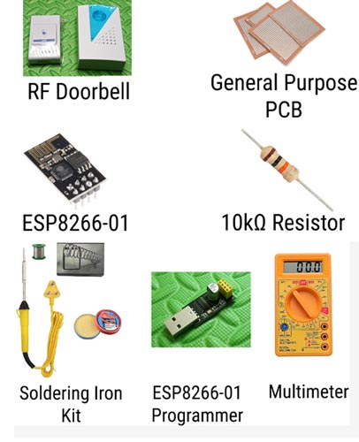
Project Used Hardware
- RF doorbell set,
- ESP8266-01 WIFI module,
- 10k Ohm resistor,
- General purpose PCB, and wires
Project Used Software
- Arduino IDE
- Libraries used: WIFIManager by tzapu and ESP8266 Webhooks by Rupak Poddar,
- IFTTT
Project Hardware Software Selection
I have chosen RF doorbell since it is more common nowadays and you don't need to handle AC voltage or wiring for modifying it. Hence, it's safer to tinker with. Also for a normal AC doorbell, the wiring is fixed to a particular point usually close to the entrance of the house whereas an RF doorbell has the freedom of being placed anywhere we want (Well within its RF range, which is decent for an average house). The brain of this project is an ESP8266-01 board. I have chosen this particular board since a. Dirt cheap. One of the cheapest microcontroller boards with WIFI capabilities on-board b. Small in size. Fits inside most (commonly available) models of the RF doorbells without hassle so we don't have any ugly wires coming out. c. Has a deep-sleep feature that lets it consume very low power in an idle state. Since RF doorbells run using batteries, we need to make our circuit power efficient. The software used is Arduino IDE since it is open-source (which means free to use) and also has tons of libraries and support communities to help out. The libraries used are WIFIManager by Tzapu: Helps us configure our smart doorbell (Connect to our home WIFI or change credentials) without having to admin/upload the code again and again onto the ESP board ESP8266 Webhooks by Rupak Poddar: Helps us connect to the IFTTT webhooks with minimal code.
Circuit Diagram

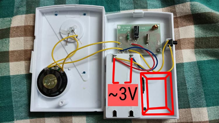
The circuit is very simple, All you have to connect is +ve and -ve supply directly to the ESP board since the 2xAA batteries voltage range is within the operational range of our ESP board (2.7V to 3.3V). And since we are using the deep sleep feature, the board will not consume much power in an idle state. And then one signal pin from the speaker output pin of the doorbell to the Reset pin of ESP.
The REST pin is also connected to the positive terminal through a 10K ohm resistor in order to keep it high by default (Pullup resistor). When a low pulse is sent to this pin, the board resets and wakes up to execute the code inside. This low pulse is completed when the speaker finishes playing the tone.
The workflow goes as follows: -
- When someone pressed the doorbell button, the transmitter sends a signal to the receiver
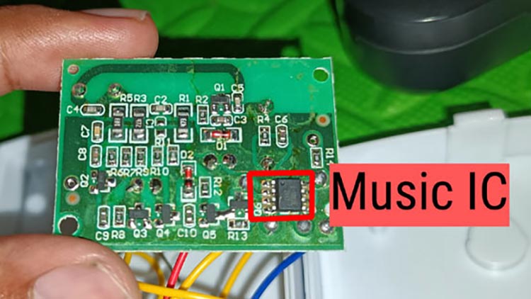
- The receiver unit, once the signal gets to it, will power up the music generating IC and hence starts lighting up the LED and speaker.
- Our ESP board which by default is in deep-sleep mode, wakes up when there is a power sent to the speaker.
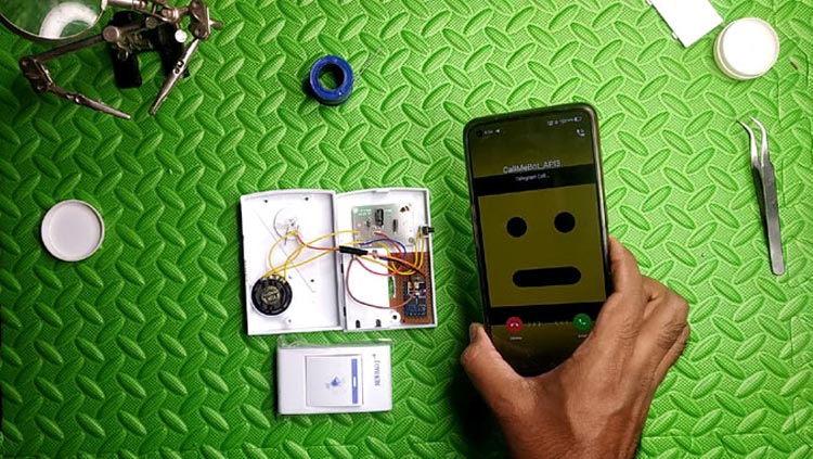
- Once awake, the ESP connects to WiFi, pings the webhooks server, and goes back into deep-sleep mode immediately.
- The webhooks in turn run an applet created in IFTTT which takes the predefined action, like sending a notification or call.
Complete Project Code
// If unable to connect to WIFI, the config portal opens and stays for 2 mins after which it goes into deepsleep

#include <WiFiManager.h> // https://github.com/tzapu/WiFiManager
#include <ESP8266Webhook.h> // By Rupak Poddar
#include <ESP8266WiFi.h>
#define KEY "YOUR_WEBHOOKS_KEY_HERE"        // Webhooks Key
#define EVENT "YOU_WEBHOOKS_EVENT_NAME"      // Webhooks Event Name
WiFiManager wm;
Webhook webhook(KEY, EVENT);    // Create an object.
int timeout = 180; // seconds to run for
int startTime = 0;
bool ds = false;
void setup() {
  WiFi.mode(WIFI_STA); // explicitly set mode, esp defaults to STA+AP
  wm.setConfigPortalBlocking(false);
  Serial.begin(115200);
  startTime = millis();
  bool res;
  res = wm.autoConnect("EspDoorBell", "password"); // password protected ap

  if (!res) {
    Serial.println("Failed to connect");
    digitalWrite(LED_BUILTIN, LOW);
  }
  else {
    //if you get here you have connected to the WiFi
    Serial.println("connected...yeey :)");
    int response = webhook.trigger();
    if (response == 200)
    {
      Serial.println("Webhook Trigger OK");
      ds = true;
      Serial.println("Entering Deep Sleep Mode");
      ESP.deepSleep(0);
    }
    else
    {
      Serial.println("Webhook Trigger Failed");
    }
  }

}

void loop() { //We enter this loop only when the board was unable to connect to saved WiFi or for the first time
  wm.process();
  if (millis() - startTime > timeout*1000 && !ds) //Keep configuration portal on for time specified by timeout
  {
    ds = true;
    Serial.println("Entering Deep Sleep Mode");
    ESP.deepSleep(0);
  }

}
Comments
Also, I assume that the Doorbell and the phone will ring simultaneously?
Hello author, I read your article, this is a great project, thank you for sharing, by the way, I believe this is not limited to doorbells, I want to make this one (without using RF wireless doorbell circuit board) to become an emergency The call button device will be used by my family and my parents (elderly people) As long as they simply operate it, they press the button and the calling method is IFTTT (I will modify the code and want to use it in LINE method)) I will go home quickly to deal with things
The RESET of ESP-01 is connected to the button end, and the other end is connected to ground (-)

Hello
Excellent project.
However, can you add a keypad, I would prefer a glass keypad for outdoor use? The idea is that we can give a password to those that we want to press the doorbell. Otherwise all day long people will be pressing the doorbell for either begging, or simply being a nuisance.
Thank you for a good project.