
Doorbell is a very common and useful device used in every household. Among electronics students and hobbyists, the doorbell circuit project is quite popular. So, in this tutorial, we are going to build a simple musical doorbell using UM66T melody generator IC. This a very simple and interesting project that requires very few components. The main feature of this doorbell is that we can control the time duration for which it keeps ringing upon pressing the switch using a time delay circuit. We have already built a Doorbell using 555 IC; you can also check it out for more inspiration.
Components Required
- UM66T-19L Melody Generator IC
- 100uF Capacitor
- 2×BC547 Transistor
- 1KΩ Resistor
- Push Button Switch
- 8 Ohm Speaker
- 3.7 Volt Battery
UM66T Melody Generator IC
The UM66T series is a CMOS LSI-designed melody generator IC to be used in the doorbell, phone, toys, musical bell indoors, home security alarm systems, and burglar alarms application. It has an on-chip ROM programmed for musical performance. The IC works on a supply voltage range of 1.5V to 4.5V. And with a built-in RC oscillator, a compact melody module can be used with only a few additional components. UM66TXX series ICs can generate different types of tones, the tone depends on the model of UM66TXX series IC’s. UM66T is a three-pin IC that looks like a transistor. The first pin is GND, the second is VCC, and the third is the OUT.
UM66T Features & Specifications:
- 64-Note Rom memory
- 1.5V ~ 4.5V power supply and low power consumption
- Built-in RC oscillator
- Level-hold mode to play repeatedly
- Power-on reset: melody begins from the first note
Circuit Diagram for Musical Doorbell
The schematic for the Musical Doorbell using UM66T is given below.

The doorbell circuit consists of a UM66T, two BC547 transistors, an 8-ohm speaker, and a couple of resistors and capacitors. Transistor T1, Resistor R1, and Capacitor C1 on the input side are used to form a time delay circuit to set the duration for which the bell sounds. The BC547 transistor functions as a switch and triggers ON/OFF. UM66T IC is internally programmed to play a specified tune as soon as a 3V is applied across its supply terminals. Here, if once the push button is pressed, capacitor C1 is charged and the transistor T1 keeps the IC playing the music till it ends. The time for the IC to play depends on discharging time of the capacitor which can be set by Resistor R1. Here, I used a 100K resistor for full tone.
Transistor T2 drives the speaker. Pin 3 of UM66 IC is connected to the base of transistor T2. Since the output from the pin3 of IC could be very low in current, it needs amplification before the programmed sound can become loud and audible across a given area. The transistor T2 is used to accept the weak sound signals from the output pin of IC and amplify it over the connected 8-ohm speaker.
Building the Circuit on Perf Board
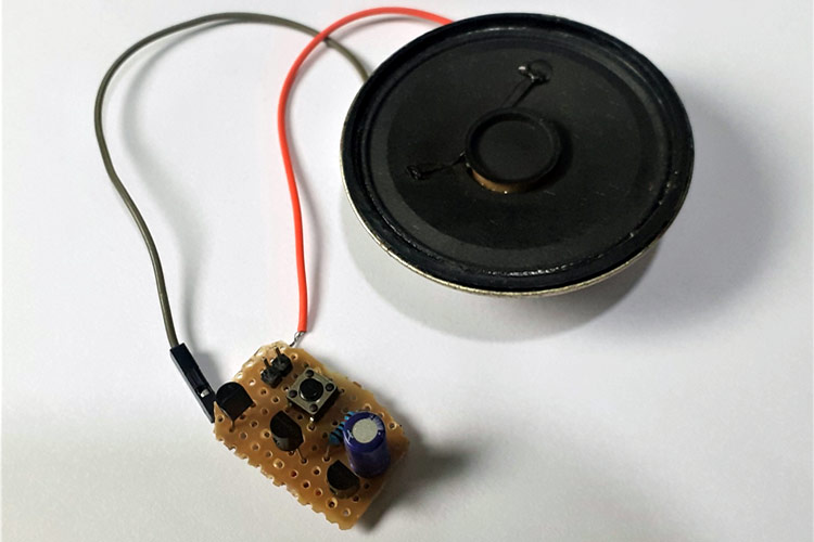
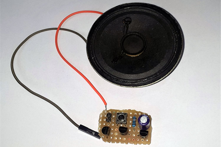
The complete circuit shown above is soldered onto a perf board. Make sure to use wires to leave enough distance to mount the IC and Transistors. My perf board is shown below:
Working of Musical Door Bell using UM66T
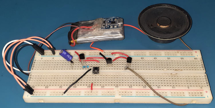
Make the connections are as per the circuit diagram and power the setup with a 3.7V Lipo battery. When powered, the Capacitor C1 charges to its full capacity. When the push button is pressed UM66T gets 3V across its supply terminals and starts playing the tune until the capacitor gets discharged. The duration for which the bell sounds can be easily changed by replacing the R1 resistor with a potentiometer.
The complete working of the project can be found in the video given below. If you have any questions, feel free to write them in the comment section below.

Hello, is there a way to cut off the sound when it gets to a lower voltage which will stop the slowing of the tune?