

3D printers have become an essential aspect of quick prototyping and have reached out to a wide range of makers and engineers. But most of these printers are hobby grade and hence require constant tinkering and repairs to keep them working. Among all challenges, 3D printer filament breaking or tangling is one of the most common problems that everyone who uses a 3D printer has encountered at some point, as a lot of print and filament gets wasted because of this issue. To avoid this issue, we'll use Filament Sensors, which will allow your printer to recognize when it's out of filament and stop printing while you change spools.
Today I'll demonstrate how to create a 3D printed smart filament sensor on perf board using an optical encoder sensor and a controller. I designed a separate sensor housing for our filament sensor since I wanted to utilize it on other printers as well. When the filament stops moving due to breakage or tangling, this Filament Sensor will beep to alert you.
You can check out the demonstration video given below-
Material Required to build a DIY Filament Runout Sensor
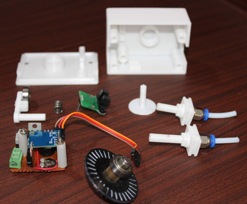
For Sensing mechanism part:
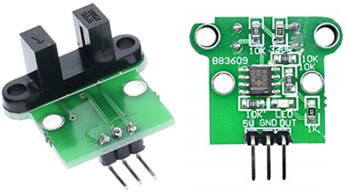
- BB3609 Optical encoder sensor X 1
- Bearing 625 X 3
- M5 30mm Allen Bolt with Nut X 1
- PC4 M5 Pneumatic Coupler X 2
- Spring X 1
For Controller and buzzer part:
- AT-Tiny 85 X 1
- DPDT Push to on Switch
- 2 Pin wire Connector
- 7805
- 7812
- Active Buzzer 5V
- Female Bergstrip
How Filament Sensor Works
Since there are two types of filament sensors, one detects the presence of filament using a limit switch and the other uses optical rotary encoders to feel the velocity of the filament moving within. Each filament sensor has its own set of advantages and disadvantages.
The one with the limit switch is for filament runover or when the extruder motor tends to run dry due to filament breaking. It is, nevertheless, simple to set up and maintain because of its simplicity and absence of moving components, and its compactness makes it more useful. However, it will not be engaged if the filament breaks near the sensor's output since the filament's presence will still be there after the filament breakup.
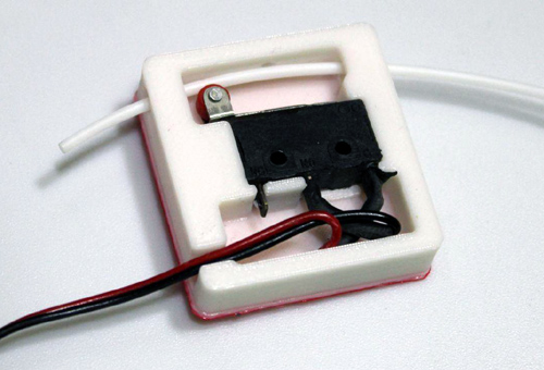
Fig1: In the above image, you can see despite the fact that the filament is broken at the output, the switch still indicates the filament's presence
When it comes to the optical rotary-based sensor, it will notify you regardless of the location and extent of the filament breakage. When the filament tangling causes the filament to halt, it will beep. Now, if the filament breaks anywhere and is unable to reach the extruder motor in any manner, the sensor will beep, indicating that something went wrong.
Because we are more concerned with precision and effectiveness, we will build our filament sensor using an optical rotary sensor MOC7811-based module, which will ensure that the filament moves continuously.
Here you can view the current Sensors that are available on the market.
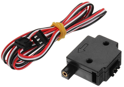
Fig 2: Limit Switch based Filament Sensor that can detect the presence of the filament within

Fig 3: The above image shows a Rotary encoder based sensor that senses the presence as well as the movement of the filament
Motion-based Filament Sensor
Since we've spoken about the benefits and drawbacks of the limit switch sensor. Now let's talk about the filament motion-based Sensors.
These sensors are Smart Filament Sensors, which are incredibly accurate and useful in detecting filament clogging, tangling, and breaking, among other things.
The sensor we'll build will allow us to modify the time delay or inactivity of the filament movement, which will be determined by the printing quality and speed. If the filament traversal speed is sluggish, the printing speed is also slow. For personalization, we'll create a rotor that will be mounted to the potentiometer's knob. It will also contain a deactivate sensor button, which will turn off the sensor when it is not in use.

You can see the final connection in the below image.
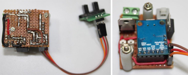
I have used a ATtiny 85 digispark board for detecting the rotation and controlling the buzzer.
Programming AT-Tiny 85
I used Arduino IDE to program the ATtiny85 digispark board. If you're new to Digispark Boards and want to learn how to program ATtiny85 with the Arduino IDE, click the link.
We have previously made many exciting projects using this ATtiny85 controller, you can check that out.
The following program is written such that every time the rotary wheel moves with filament, an interrupt is triggered.
#include <avr/io.h>
#include <avr/interrupt.h>
// Define pins for switch the LED, plus the chosen interrupt for reacting to
#define INTERRUPT_PIN PCINT1  // This is PB1 per the schematic
#define INT_PIN PB1 // ON Board LED Interrupt pin of choice: PB1 (same as PCINT1) - Pin 6
#define LED_PIN PB4 // PB4 - Pin 3
#define BUZZ PB0
#define PCINT_VECTOR PCINT0_vect // This step is not necessary - it's a naming thing for clarity
// FYI: Variables used within ISR must be declared Volatile.
// static volatile byte LEDState;
// The setup function runs only once when the ALU boots
void setup() {
    pinMode(LED_PIN, OUTPUT);  // Set our chosen LED visual feedback as an output pin (PB4 / Pin 3)
    pinMode(BUZZ, OUTPUT);
    digitalWrite(LED_PIN, HIGH); // Blink to show it's booting up and your LED is wired correctly
    delay(500);
    digitalWrite(LED_PIN, LOW);
    delay(500);
    // Code here is the key piece of configuring and enabling the interrupt
    cli(); // Disable interrupts during setup
    PCMSK |= (1 << INTERRUPT_PIN); // Enable interrupt handler (ISR) for our chosen interrupt pin (PCINT1/PB1/pin 6)
    GIMSK |= (1 << PCIE);  // Enable PCINT interrupt in the general interrupt mask
    pinMode(INT_PIN, INPUT_PULLUP);   // Set our interrupt pin as input with a pullup to keep it stable
    sei();  //last line of setup - enable interrupts after setup
}
unsigned long current_millis=0;
unsigned long prev_millis=0;
int interval;
void loop() {
  // Put any general processing code in the main loop
  // Be aware - if the INT_PIN changes state, the loop will be suspended while the ISR runs to completion
  interval=map(analogRead(1),0,1023,0,20);
  current_millis=millis();
  if ((unsigned long)(current_millis-prev_millis)>=interval*1000)
  {
    digitalWrite(BUZZ,1);
    delay(50);
    digitalWrite(BUZZ,0);
    delay(50);
    digitalWrite(BUZZ,1);
    delay(50);
    digitalWrite(BUZZ,0);
    delay(50);
    digitalWrite(BUZZ,1);
    delay(50);
    digitalWrite(BUZZ,0);
    delay(50);
    digitalWrite(BUZZ,1);
    delay(50);
    digitalWrite(BUZZ,0);
    delay(150);
   }
}
// This is the interrupt handler called when there is any change on the INT_PIN
// ISR is defined in the headers - the ATtiny85 only has one handler
ISR(PCINT_VECTOR)
{ prev_millis=millis();
  if( digitalRead(INT_PIN) == HIGH ) {
    digitalWrite(LED_PIN, HIGH);
  }else{
    digitalWrite(LED_PIN, LOW);
  }
}
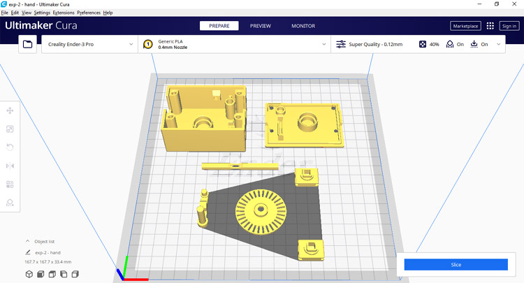
3D Design of the Enclosure
I got the idea from Thingiverse. There, I came across a design that was exactly what I needed. Unfortunately, I was unable to locate all of the needed components included in that design's BOM, so I had to modify the design, which you may obtain from the provided links. The controller circuit needed to be housed in its own add-on box now.
Here you can find the images of the design.
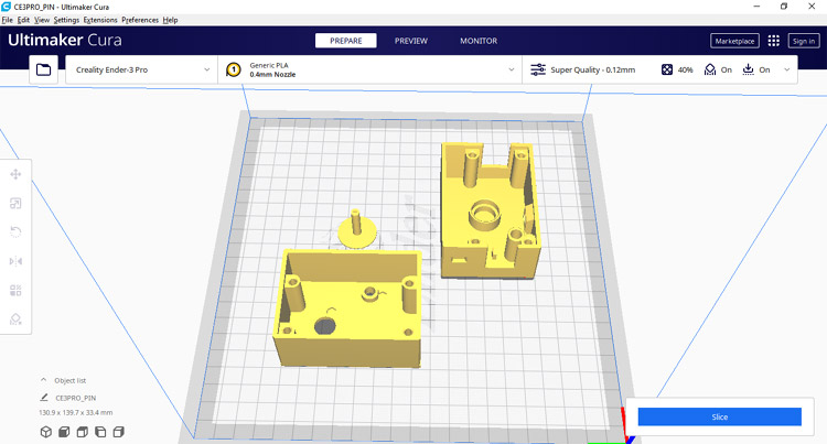
I have changed the spring holder and other attachments for the circuit we have made. Modified Design is as follows.
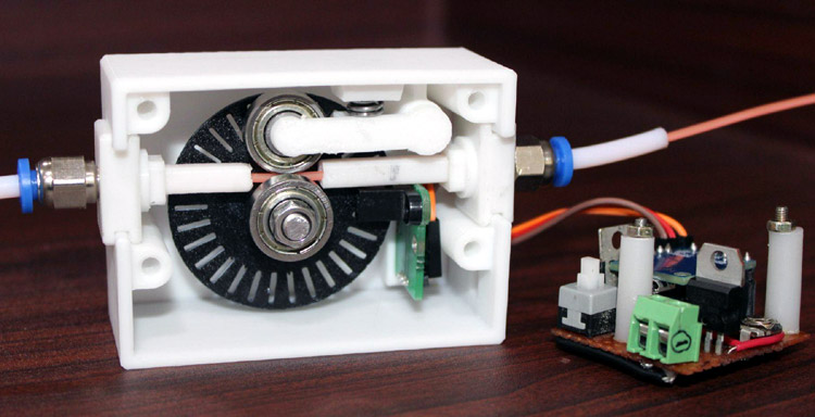
And this is the final outlook of our 3D Printer Filament Runout Sensor.
Conclusion
Hence we have made our own smart filament Sensor using an optical encoder sensor and AT tiny 85 Controller. I hope you have enjoyed the project. For any queries please refer to our forum.
Complete Project Code
#include <avr/io.h>
#include <avr/interrupt.h>
// Define pins for switch the LED, plus the chosen interrupt for reacting to
#define INTERRUPT_PIN PCINT1  // This is PB1 per the schematic
#define INT_PIN PB1           // ON Board LED Interrupt pin of choice: PB1 (same as PCINT1) - Pin 6
#define LED_PIN PB4           // PB4 - Pin 3
#define BUZZ PB0
#define PCINT_VECTOR PCINT0_vect      // This step is not necessary - it's a naming thing for clarity
// FYI: Variables used within ISR must be declared Volatile.
// static volatile byte LEDState;
// The setup function runs only once when the ALU boots
void setup() {
    pinMode(LED_PIN, OUTPUT);         // Set our chosen LED visual feedback as an output pin (PB4 / Pin 3)
    pinMode(BUZZ, OUTPUT);
    digitalWrite(LED_PIN, HIGH);      // Blink to show it's booting up and your LED is wired correctly
    delay(500);
    digitalWrite(LED_PIN, LOW);
    delay(500);
    // Code here is the key piece of configuring and enabling the interrupt
    cli();                            // Disable interrupts during setup
    PCMSK |= (1 << INTERRUPT_PIN);    // Enable interrupt handler (ISR) for our chosen interrupt pin (PCINT1/PB1/pin 6)
    GIMSK |= (1 << PCIE);             // Enable PCINT interrupt in the general interrupt mask
    pinMode(INT_PIN, INPUT_PULLUP);   // Set our interrupt pin as input with a pullup to keep it stable
    sei();                            //last line of setup - enable interrupts after setup
}
unsigned long current_millis=0;
unsigned long prev_millis=0;
int interval;
void loop() {
  // Put any general processing code in the main loop
  // Be aware - if the INT_PIN changes state, the loop will be suspended while the ISR runs to completion
  interval=map(analogRead(1),0,1023,0,20);
  current_millis=millis();
  if ((unsigned long)(current_millis-prev_millis)>=interval*1000)
  {
    digitalWrite(BUZZ,1);
    delay(50);
    digitalWrite(BUZZ,0);
    delay(50);
    digitalWrite(BUZZ,1);
    delay(50);
    digitalWrite(BUZZ,0);
    delay(50);
    digitalWrite(BUZZ,1);
    delay(50);
    digitalWrite(BUZZ,0);
    delay(50);
    digitalWrite(BUZZ,1);
    delay(50);
    digitalWrite(BUZZ,0);
    delay(150);
   }
}
// This is the interrupt handler called when there is any change on the INT_PIN
// ISR is defined in the headers - the ATtiny85 only has one handler
ISR(PCINT_VECTOR)
{ prev_millis=millis();
  if( digitalRead(INT_PIN) == HIGH ) {
    digitalWrite(LED_PIN, HIGH);
  }else{
    digitalWrite(LED_PIN, LOW);
  }
}
