

Human brain is built of complex layer of structures which helps us to be a dominant species on earth. For example the entorhinal cortex in your brain can give you sense of direction helping you to navigate easily through places that you are not familiar with. But unlike us, Robots and unmanned Ariel vehicles need something to get this sense of direction so they could manoeuvre autonomously in new terrains and landscapes. Different robots use different types of sensors to accomplish this, but the commonly used one is a magnetometer, which could inform the robot in which geo-graphic direction it is currently facing at. This will not only help the robot to sense direction but also to take turns in a pre-defined direction and angel.
Since the sensor could indicate the geo-graphic North, South, East and West, we humans could also use it at times when required. So in this article let us try to understand how Magnetometer sensor works and how to interface it with a microcontroller like Arduino. Here we will build a cool Digital Compass which will help us in finding the directions by glowing an LED pointing North Direction. This Digital Compass is neatly fabricated on PCB from PCBGOGO, so that I can carry it next time when I go out in the wild and wish that I would get lost just to use this thing for finding my way back home. Let’s get started.
Materials Required for Arduino Compass Project
- Arduino Pro mini
- HMC5883L Magnetometer sensor
- LED lights - 8Nos
- 470Ohm Resistor – 8Nos
- Barrel Jack
- A reliable PCB manufacturer like PCBgogo
- FTDI Programmer for mini
- PC/Laptop
What is a Magnetometer and How does it Work?
Before we dive into the circuit, let’s understand a bit about magnetometer and how they work. As the name suggests the term Magneto does not refer to that crazy mutant in marvel who could control metals by just playing piano in the air. Ohh! But I like that guy he is cool.
Magnetometer is actually a piece of equipment that could sense the magnetic poles of the earth and point the direction according to that. We all know that Earth is huge piece of spherical magnet with North Pole and South Pole. And there is magnetic field because of it. A Magnetometer senses this magnetic field and based on the direction of the magnetic field it can detect the direction we are facing.
How the HMC5883L Sensor Module Works
The HMC5883L being a magnetometer sensor does the same thing. It has the HMC5883L IC on it which is from Honeywell. This IC has 3 magneto-resistive materials inside which are arranged in the axes x, y and z. The amount of current flowing through these materials is sensitive to the earth’s magnetic field. So by measuring the change in current flowing through these materials we can detect the change in Earth’s magnetic field. Once the change is magnetic field is absorbed the values can then be sent to any embedded controller like a microcontroller or processor through the I2C protocol.
Since the sensor works by sensing the magnetic field, the output values will be greatly affected if a metal is placed nearby. This behavior can be leveraged to use these sensors as metal detectors also. Care should be taken not to bring magnets near this sensor since the strong magnetic field from a magnet might trigger false values on the sensor.
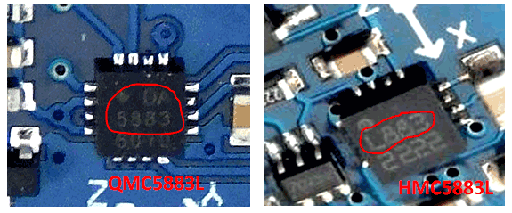
Difference between HMC5883L and QMC5883L
There is a common confusion revolving around these sensors for many beginners. This is because some vendors (actually most) sell the QMC5883L sensors instead of the original HMC5883L from Honeywell. It is mostly because the QMC5883L is way cheaper than the HMC5883L module. The sad part is that the working of these two sensors is slightly different and the same code cannot be used for both. This is because the I2C address of both the sensors is not the same. The code give in this tutorial will work only for QMC5883L the commonly available sensor module.

To know which model of sensor you are having, you just have to look up closely at the IC itself to read what is written on top of it. If it is written something like L883 then it is the HMC58836L and if it is written something like DA5883 then it is the QMC5883L IC. Both the modules are shown in picture below for easy understating.
Arduino Digital Compass Circuit Diagram
The circuit for this Arduino based Digital Compass is pretty simple, we simply have to interface the HMC5883L sensor with the Arduino and connect 8 LEDs to the GPIO pins of the Arduino Pro mini. The complete circuit diagram is shown below

The Sensor module has 5 pins out of which the DRDY (Data Ready) is not used in our project since we are operating the sensor in continuous mode. The Vcc and ground pin is used to power the Module with 5V from the Arduino board. The SCL and SDA are the I2C communication bus lines that are connected to the A4 and A5 I2C pins of the Arduino Pro mini respectively. Since the module itself has a pull high resistor on the lines, there is no need to add them externally.
To indicate the direction we have used 8 LEDs all of which are connected to the GPIO pins of the Arduino through a current limiting resistor of 470 Ohms. The Complete circuit is powered by a 9V battery through the barrel Jack. This 9V is provided directly to the Vin pin of the Arduino where it is regulated to 5V using the on-board regulator on Arduino. This 5V is then used to power the sensor and the Arduino as well.
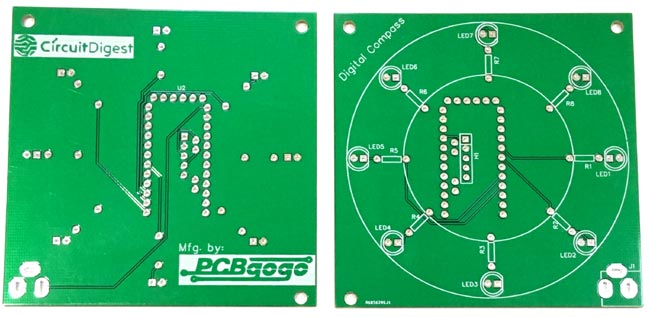
Fabricating the PCBs for the Digital Compass
The idea of the circuit is place the 8 LEDs in a circular fashion so that each Led points all the 8 directions namely North, North-East, East, South-East, South, South-West, West and North West respectively. So it is not easy to arrange them neatly on a breadboard or even on a perf board for that matter. Developing a PCB for this circuit will make it look more neat and easy to use. So I opened my PCB designing software and placed the LEDs and resistor in a neat circular pattern and connected the tracks to form the connections. My Design looked something like this below when completed. You can also download the Gerber file from the link given below.
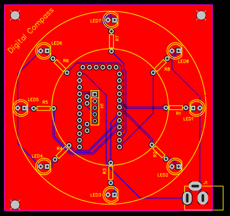
I have designed it to be a double side board since I want the Arduino to be in the bottom side of my PCB so that it does not spoil the look on top of my PCB. If you are worrying that you have to pay high for a double side PCB then hold on I got good new coming.
Now, that our Design is ready it is time to get them fabricated. To get the PCB done is quite easy, simply follow the steps below
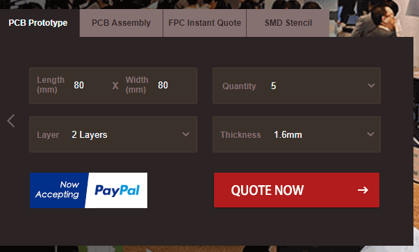
Step 1: Get into www.pcbgogo.com, sign up if this is your first time. Then, in the PCB Prototype tab enter the dimensions of your PCB, the number of layers and the number of PCB you require. My PCB is 80cm×80cm so the tab looks like this below
Step 2: Proceed by clicking on the Quote Now button. You will be taken to a page where to set few additional parameters if required like the material used track spacing etc. But mostly the default values will work fine. The only thing that we have to consider here is the price and time. As you can see the Build Time is only 2-3 days and it just costs only $5 for our PSB. You can then select a preferred shipping method based on your requirement.
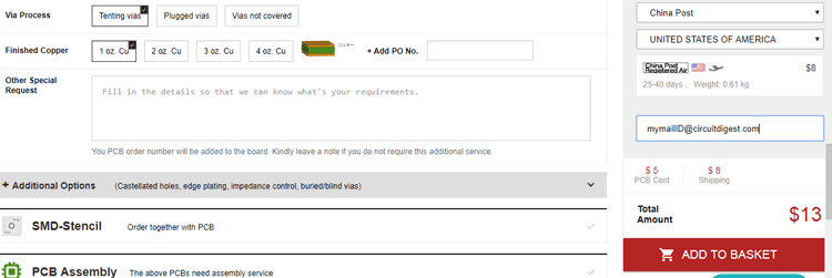
Step 3: The final step is to upload the Gerber file and proceed with the payment. To make sure the process is smooth PCBGOGO verifies if your Gerber file is valid before proceeding with the payment. This way you can sure that your PCB is fabrication friendly and will reach you as committed.
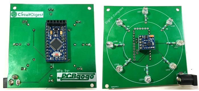
Assembling the PCB
After the board was ordered, it reached me after some days though courier in a neatly labeled well packed box and like always the quality of the PCB was awesome. I am sharing few pictures of the boards below for you to judge.
I turned on my soldering rod and started assembling the Board. Since the Footprints, pads, vias and silkscreen are perfectly of the right shape and size I had no problem assembling the board. The board was ready in just 10 minutes from the time of unpacking the box.
Few pictures of the board after soldering are shown below.
Programming the Arduino
Now that our hardware is ready, let us look into the program that has to be uploaded into our Arduino board. The purpose of the code is to read the data from the QMC5883L magnetometer sensor and convert it into degree (0 to 360). Once we know the degree, we have to turn on a the LED pointing a specific direction. The direction I have used in this program is north. So irrespective of where you are there will only be one LED glowing on your board and the direction of the LED will indicate the NORTH direction. Once could later calculate the other direction is one direction is known.
The complete code for this Digital Compass Project can be found at the end of this page. You can directly upload it on your board after including the library and you are ready to go. But, if you want to know more on what is actually happening in the code read further.
As told earlier we are using the QMC5883L IC, to communicate with the IC we need to know the I2C address of its registers which can be found in its datasheet. But lucky for us all of that is already done and is packaged as a library by a guy called keepworking on Github. So all you have to do is simply download the Library for QMC5883L by clicking on the link to get a ZIP file. This ZIP file can then be added into your Arduino IDE by following Sketch -> Include Library -> Add .ZIP library.
After the Library is added, we can proceed with our program. We begin the program by including the required library files as shown below. The wire library is used to enable I2C communication and the MechaQMC5883 is the one that we just added to Arduino. This library holds all the information on how to talk with the EMC5883L sensor.
#include <Wire.h> //Wire Librarey for I2C communication
#include <MechaQMC5883.h> //QMC5883 Librarey is added since mine is QMC583 and not HMC5883
In the next line, we create an object name for the sensor we are using. I have used the name qmc but it can be anything you like.
MechaQMC5883 qmc; //Create an object name for the snsor, I have named it as qmc
Next, we get into the global variable declarations. Here since we have 8 Led as outputs, it is hard to refer to each one through pin name, so we are using the array option to refer to all the LEDs. The name of the array is ledPins and the variable led_count is the number of led we have. It starts with 0.
int ledPins[] = {2,3,4,5,6,7,8,9}; //Array of output pin to which the LED is connected to
char led_count = 7; //Total number of LED pins
Inside the void setup function, we initialize the I2C communication, Serial communication and the sensor as well. Then we declare all the LED pins as output pins. Since we have used an array, it is easy to refer to all the pins by using a for loop and navigating through the for loop as shown below.
void setup() {
  Wire.begin(); //Begin I2C communication
  Serial.begin(9600); //Begin Serial Communication
  qmc.init(); //Initialise the QMC5883 Sensor

  for (int thisPin=0; thisPin <= led_count; thisPin++){ //Navigate through all the pins in array
    pinMode(ledPins[thisPin],OUTPUT); //Declare them as output
  }
}
In the main loop which is an infinite one, we have to get the values of x,y and z from the sensor and calculate the degree the sensor is currently facing. To read the values of x,y and z use the following line
int x,y,z;
qmc.read(&x,&y,&z); //Get the values of X,Y and Z from sensor
The formulae to calculate the heading in degree is shown below. Since we are not going to rotate the compass along the z axis we do not take that value into account. This formulae can be used only if the IC flat surface is facing up like it is in our set-up. Once heading is calculated, the value will be in range -180 to 180 which we have to convert to 0 to 360 like we would find in all digital compasses.
int heading=atan2(x, y)/0.0174532925; //Calculate the degree using X and Y parameters with this formulae
 //Convert result into 0 to 360
  if(heading < 0)
  heading+=360;
  heading = 360-heading;
The final step is to glow the LED pointing in the NORTH direction. To do that we have series of if conditions statements where we check in what range the degree is currently in and turn on the LED according to that. The code is show below
//Based on the value of heading print the result for debugging and glow the respective LED.
  if (heading > 338 || heading < 22)
  {
    Serial.println("NORTH");
    digitalWrite(ledPins[0],HIGH);
  }

  if (heading > 22 && heading < 68)
  {
    Serial.println("NORTH-EAST");
    digitalWrite(ledPins[7],HIGH);
  }

  if (heading > 68 && heading < 113)
  {
    Serial.println("EAST");
    digitalWrite(ledPins[6],HIGH);
  }

  if (heading > 113 && heading < 158)
  {
    Serial.println("SOUTH-EAST");
    digitalWrite(ledPins[5],HIGH);
  }

  if (heading > 158 && heading < 203)
  {
    Serial.println("SOUTH");
    digitalWrite(ledPins[4],HIGH);
  }

  if (heading > 203 && heading < 248)
  {
    Serial.println("SOTUH-WEST");
    digitalWrite(ledPins[3],HIGH);
  }

  if (heading > 248 && heading < 293)
  {
    Serial.println("WEST");
    digitalWrite(ledPins[2],HIGH);
  }

  if (heading > 293 && heading < 338)
  {
    Serial.println("NORTH-WEST");
    digitalWrite(ledPins[1],HIGH);
  }
The logic behind the code values can be understood by looking at the table below. Basically we calculate which direction we are facing and predict the north direction and glow the respective LED.
|
Direction |
Degree corresponding to Direction |
Range for that Direction |
|
NORTH |
0° / 360° |
>338° or < 22° |
|
NORTH-EAST |
45° |
22° to 68° |
|
EAST |
90° |
68° to 113° |
|
SOTUH-EAST |
135° |
113° to 158° |
|
SOUTH |
180° |
158° to 203° |
|
SOUTH-WEST |
225° |
203° to 248° |
|
WEST |
170° |
248° to 293° |
|
NORTH-WEST |
315° |
293° to 338° |
The final part of the program is to set how fast the result has to be updated. I have create a delay for 500 milli seconds and then made all the LED to turn off to start again form the first inside the void loop. But if you need faster updates you can reduce the delay further down.
  delay(500); // update position of LED for every alf seconds
//Turn off the all the LED
    for (int thisPin=0; thisPin <= led_count; thisPin++){
     digitalWrite(ledPins[thisPin],LOW);
  }
Testing the Digital Compass
Since we have used the Arduino pro mini we need an external programmer like an FTDI board to upload the program. Once the program is uploaded, you should notice one LED is glowing on the board, the direction in which the LED is glowing will be the NORTH direction.
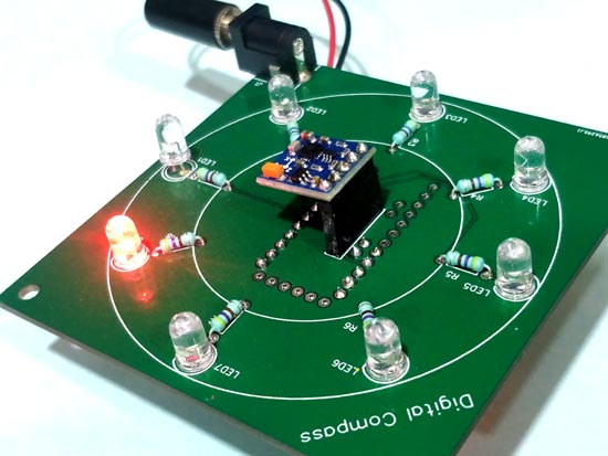
You can then play with the Board by rotating it and check if the LED still points to the north direction. After that you can use a 9V battery anytime to power the set-up and check the direction you are facing. The complete working of the Digital compass can be found in the video below. You may note that the values will get wrong when there is a heavy metal piece near your board or even if you rotate the board along the Z axis. There are ways to overcome this problem and that is for another tutorial.
Hope you have enjoyed the tutorial and learned something useful out of it. If yes, then the credits go to PCBGOGO who have sponsored this post, so do give them a try for your PCB’s. Like always post your thoughts on the comment section below.
Complete Project Code
/*

 * Program for Arduino Digital Compass using QMC5883

 * Project by: Aswinth Raj

 * Dated: 1-11-2018

 * Website: www.circuitdigest.com

 * Lib. from https://github.com/keepworking/Mecha_QMC5883L

 * WARNING: This code works only for QMC5883 Sensor which is commonly being sold as HMC5883 read article to find the actual name of the sensor you have.

 */

#include <Wire.h> //Wire Librarey for I2C communication

#include <MechaQMC5883.h> //QMC5883 Librarey is added since mine is QMC583 and not HMC5883
MechaQMC5883 qmc; //Create an object name for the snsor, I have named it as qmc
int ledPins[] = {2,3,4,5,6,7,8,9}; //Array of output pin to which the LED is connected to

char led_count = 7; //Total number of LED pins


void setup() {

  Wire.begin(); //Begin I2C communication

  Serial.begin(9600); //Begin Serial Communication

  qmc.init(); //Initialise the QMC5883 Sensor
  for (int thisPin=0; thisPin <= led_count; thisPin++){ //Navigate through all the pins in array

    pinMode(ledPins[thisPin],OUTPUT); //Declare them as output

  }
}
void loop() { //Infinite Loop

  int x,y,z;

  qmc.read(&x,&y,&z); //Get the values of X,Y and Z from sensor


  int heading=atan2(x, y)/0.0174532925; //Calculate the degree using X and Y parameters with this formulae
 //Convert result into 0 to 360

  if(heading < 0)

  heading+=360;

  heading = 360-heading;


  Serial.println(heading); //Print the value of heading in degree for debugging
//Based on the value of heading print the result for debugging and glow the respective LED.

  if (heading > 338 || heading < 22)

  {

    Serial.println("NORTH");

    digitalWrite(ledPins[0],HIGH);

  }

  if (heading > 22 && heading < 68)

  {

    Serial.println("NORTH-EAST");

    digitalWrite(ledPins[7],HIGH);

  }

  if (heading > 68 && heading < 113)

  {

    Serial.println("EAST");

    digitalWrite(ledPins[6],HIGH);

  }

  if (heading > 113 && heading < 158)

  {

    Serial.println("SOUTH-EAST");

    digitalWrite(ledPins[5],HIGH);

  }

  if (heading > 158 && heading < 203)

  {

    Serial.println("SOUTH");

    digitalWrite(ledPins[4],HIGH);

  }

  if (heading > 203 && heading < 248)

  {

    Serial.println("SOTUH-WEST");

    digitalWrite(ledPins[3],HIGH);

  }

  if (heading > 248 && heading < 293)

  {

    Serial.println("WEST");

    digitalWrite(ledPins[2],HIGH);

  }

  if (heading > 293 && heading < 338)

  {

    Serial.println("NORTH-WEST");

    digitalWrite(ledPins[1],HIGH);

  }

  delay(500); // update position of LED for every alf seconds

//Turn off the all the LED

    for (int thisPin=0; thisPin <= led_count; thisPin++){

     digitalWrite(ledPins[thisPin],LOW);

  }

}
Comments
Can I use the MPU6050 for thr HMC5883L or is thise not possible

Hi, I was wondering where the link is to the Gerber files. Thanks.