
By shiva shankar P
Most existing home automation systems emphasize remote access rather than intelligent automation. Users are required to manually select modes, configure schedules, or control devices individually through applications. This approach makes the system reactive and increases operational effort. From a system design perspective, the limitation lies in the absence of centralized decision logic that can understand context and act automatically. CM³ is developed to address this limitation by introducing a centralized mode management engine that adapts in real time to environmental conditions and user presence. Once configured, the system operates autonomously without requiring frequent user input.
Objective of CM³
The objectives of CM³ are as follows
- Centralize decision making across multiple devices
- Enable instant adaptation based on real-time conditions
- Reduce user involvement after initial configuration
- Ensure reliable operation without cloud dependency
- Allow flexible mode configuration based on user needs
System Architecture Overview
CM³ is designed using a centralized intelligence with distributed sensing and actuation model. The architecture separates decision logic from physical execution, which improves scalability and maintainability.
The architecture consists of
- One main control unit for global decision making
- Multiple slave units for localized sensing and control
- Wireless communication for inter-node coordination
- Event-driven data flow instead of continuous polling
This structure allows the system to expand across rooms or zones without altering the core logic.
Main Control Unit
The main control unit is implemented using the ESP32 S3 Box 3. It acts as the central engine of the CM³ system.
Responsibilities of the main unit include
- Maintaining the current operational mode
- Processing sensor events received from slave units
- Evaluating mode transition conditions
- Publishing synchronized control commands
- Providing a user interface for configuration
By centralising decision making, consistency is maintained across all connected devices.
Slave Units
Slave units are implemented using ESP32 C3 and ESP32 C6 boards. These units form the distributed execution layer of the system.
Functions of slave units include
- Interfacing with sensors
- Monitoring environmental parameters
- Controlling relays and connected loads
- Communicating status updates to the main unit
Deploying slave units close to sensors and loads reduces wiring complexity and improves response time.
Sensor Integration
CM³ integrates multiple types of sensors to capture environmental context.
Supported sensor categories include
- Motion sensors for presence detection
- Temperature sensors for thermal monitoring
- Humidity sensors for comfort assessment
- Air quality sensors for safety and health
Sensor data is processed locally at the slave level to detect state changes. Only relevant events are transmitted to the main controller, which reduces network traffic and processing overhead.
Communication Protocol
Intercommunication between the main unit and slave units is implemented using MQTT.
Key reasons for selecting MQTT
- Lightweight protocol suitable for embedded systems
- Topic-based publish and subscribe model
- Low bandwidth consumption
- Decoupled communication between nodes
Each slave unit publishes sensor events to predefined topics, while the main unit publishes mode-based control commands that subscribed slave units execute.
Mode-Based Operation
CM³ operates entirely on configurable modes rather than direct device control.
A mode defines
- The system state
- The set of active devices
- The behavior of each device
- Priority rules for execution
Modes are user-configurable and can be modified without changing hardware. When environmental conditions change, the system evaluates predefined logic and transitions to the appropriate mode, triggering coordinated actions across multiple devices.
Adaptive Decision Logic
CM³ uses event-driven logic instead of scheduled automation.
Decision logic characteristics include
- Real-time evaluation of sensor inputs
- Immediate mode transitions when conditions are met
- No dependency on fixed time schedules
- Minimal latency between detection and action
For example, motion detection can activate a presence mode, while prolonged inactivity can trigger an idle or power-saving mode automatically.
Reliability and Deployment Considerations
The system is designed for practical deployment.
Key reliability features include
- Local processing without cloud dependency
- Fast response due to on-device decision making
- Modular hardware for easy expansion
- Fail-safe relay control mechanisms
This ensures the system remains operational even during network outages.
Significance of CM³
CM³ transforms automation into a context-aware system that reacts naturally to user presence and environmental conditions. Users do not interact with individual devices but experience a responsive environment that adapts automatically. By prioritizing centralized intelligence and mode-based control, CM³ provides a scalable, practical, and intuitive automation solution.
Components Required
| Component Name | Quantity | Datasheet/Link |
| ESP 32 S3 box 3 | 1 | - |
| ESP 32 C3 or C6 boards | 2 | - |
| Relay Modules | 2 | - |
| temperature sensor (DHT22) | 2 | - |
| LDR sensor | 1 | - |
| PIR motion sensor | 1 | - |
| AQI sensor (MQ135 or any other) | 1 | - |
| PVC enclosure | 2 | - |
| switches | 2 | - |
Circuit Diagram

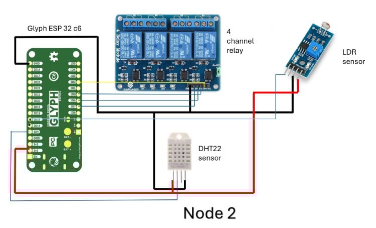
Circuit Diagram Summary (Node using ESP32-C3 / ESP32-C6)
Each node in the CM³ system is built around a Glyph ESP32 (C3 or C6) and acts as a distributed sensing and control unit. Both diagrams follow the same electrical concept; only the ESP32 variant changes.
1. Controller (ESP32-C3 / ESP32-C6)
The ESP32 serves as the local processing unit for the node.
It performs three main tasks:
- Reads sensor data
- Controls relay outputs
- Communicates with the CM³ main unit via Wi-Fi/MQTT
The ESP32 is powered using its 3.3 V pin, and all grounds are kept common to ensure signal reference stability.
2. Power Distribution
- ESP32 3.3 V pin supplies the DHT22, PIR sensor, and LDR module
- Relay module is powered using VCC and GND from the ESP32 side (logic power)
- All components share a common ground line, which is critical for correct digital and analog readings
Red wires indicate VCC, black wires indicate GND, and blue/yellow wires are signal lines.
3. DHT22 Temperature and Humidity Sensor
- VCC connected to ESP32 3.3 V
- GND connected to common ground
- Data pin connected to a single ESP32 GPIO
The DHT22 provides:
- Ambient temperature
- Relative humidity
This data is used by CM³ for comfort-based and mode-based decisions.
4. PIR Motion Sensor
- VCC connected to 3.3 V
- GND connected to common ground
- Output pin connected to a digital GPIO
The PIR sensor detects human presence or motion.
Its output is a digital HIGH/LOW signal, used for:
- Presence detection
- Occupancy-based automation
- Triggering modes like STUDY, SLEEP, or IDLE
5. LDR Light Sensor Module
- VCC connected to 3.3 V
- GND connected to common ground
- Output connected to an ESP32 GPIO (digital or analog depending on module configuration)
The LDR module detects ambient light intensity.
This is used for:
- Day/night detection
- Automatic lighting decisions
- Energy-saving logic
6. 4-Channel Relay Module
- VCC and GND connected to the ESP32 power lines
- IN1–IN4 connected to individual ESP32 GPIO pins
Each relay channel can switch an external AC or DC load.
The ESP32 drives the relay inputs to:
- Turn appliances ON or OFF
- Execute mode-based actions
- Perform centralized control via CM³ commands
Electrical isolation is provided by the relay module, protecting the ESP32 from high-voltage loads.
7. Overall Node Function
Each node operates independently for sensing and actuation, but remains logically connected to the CM³ main unit.
In summary, the node:
- Collects environmental and motion data
- Controls up to four electrical loads
- Publishes sensor data via MQTT
- Subscribes to mode and command topics
- Executes actions based on CM³ decisions
This distributed design reduces wiring complexity, improves scalability, and allows the CM³ system to expand across multiple rooms or zones.
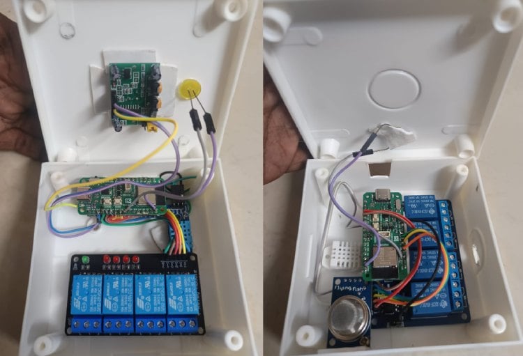
Hardware Assembly
Step 0: Before You Start (Important)
- Do NOT power anything while wiring
- Keep all jumper wires short and tight
- Identify 3.3V, GND, and GPIO pins on your ESP32 board
- Keep relay module away from low-level sensor pins
Step 1: Mount the ESP32 Board
Place the Glyph ESP32-C3 / ESP32-C6 on the enclosure base or table.
Ensure the USB port is accessible for programming.
Identify these pins clearly:
• 3V3
• GND
• At least 6 GPIO pins (for sensors + relays)
This board is the brain of the node.
Step 2: Create a Common Power Rail
This step is critical.
- Choose one GND pin on the ESP32.
- From this GND pin, connect jumper wires to:
- • DHT22 GND
- • PIR GND
- • LDR module GND
- • Relay module GND
- Choose the 3.3V pin on ESP32.
- From 3.3V, connect jumper wires to:
- • DHT22 VCC
- • PIR VCC
- • LDR module VCC
Now all sensors share the same power reference, avoiding noise and false readings.
Step 3: Connect the DHT22 Sensor
The DHT22 has 4 pins (front view, left to right).
- Pin 1 (VCC) → ESP32 3.3V
- Pin 2 (DATA) → One ESP32 GPIO (example GPIO4)
- Pin 3 → Not connected
- Pin 4 (GND) → ESP32 GND
If your DHT22 is bare (not module):
• Add a 10k pull-up resistor between DATA and 3.3V
This sensor provides temperature and humidity.
Step 4: Connect the PIR Motion Sensor
The PIR module has 3 pins.
- VCC → ESP32 3.3V
- GND → ESP32 GND
- OUT → One ESP32 GPIO (example GPIO6)
Make sure:
• PIR jumper is set to H (retrigger) if available
• Sensor dome faces outward from the enclosure
This sensor detects human presence.
Step 5: Connect the LDR Light Sensor Module
The LDR module usually has 3 pins.
- VCC → ESP32 3.3V
- GND → ESP32 GND
- OUT → ESP32 GPIO (analog-capable preferred, example GPIO1)
Adjust the onboard potentiometer:
• Clockwise → more sensitive
• Counter-clockwise → less sensitive
This sensor detects ambient light level.
Step 6: Connect the 4-Channel Relay Module (Control Side)
This step is logic wiring only, not load wiring.
- Relay VCC → ESP32 3.3V or 5V (check module rating)
- Relay GND → ESP32 GND
Now connect control pins:
3. IN1 → ESP32 GPIO (example GPIO10)
4. IN2 → ESP32 GPIO (example GPIO11)
5. IN3 → ESP32 GPIO (example GPIO12)
6. IN4 → ESP32 GPIO (example GPIO13)
Do NOT connect AC loads yet.
Step 7: Connect Relay Load Side (Final Step)
Only do this after logic testing.
For each relay channel:
- COM → Live supply line
- NO → Load input (lamp, fan, etc.)
- Neutral goes directly to load
Keep:
- High-voltage wires separated
- No loose strands
- Proper insulation
Relays provide electrical isolation from ESP32.
Step 8: Final Wiring Checklist
Before powering ON, verify:
- All GNDs are common
- No 5V accidentally connected to ESP32 GPIO
- No relay AC wiring touching ESP32 area
- Sensors powered at 3.3V
- GPIO pins are not shorted
Step 9: Power-Up and Test
- Connect ESP32 to USB
- Upload test firmware
- Verify:
- • DHT22 readings update
- • PIR toggles on motion
- • LDR changes with light
- • Relays click when commanded
Only after this, mount everything inside the enclosure.
Step 10: Node Ready for CM³
At this stage, the node:
- Reads temperature, humidity, motion, light
- Controls four appliances
- Communicates via MQTT
- Acts as a CM³ slave node
Code Explanation
ESP Codes :
1. Header Files and Libraries
#include <Arduino.h> #include <WiFi.h> #include <PubSubClient.h> #include <Preferences.h> #include <lvgl.h> #include <LovyanGFX.hpp> #include <LGFX_AUTODETECT.hpp>
Arduino.h
Provides the core Arduino framework, including setup(), loop(), millis(), delay(), and basic types.
WiFi.h
Used to connect the ESP32-S3 to a wireless network. CM³ relies on WiFi for MQTT-based intercommunication.
PubSubClient.h
Implements the MQTT client. This is the backbone of CM³ communication between the core engine and slave nodes.
Preferences.h
Provides access to ESP32’s non-volatile storage (NVS). This allows CM³ to store configuration such as modes or rules persistently.
lvgl.h
LVGL is the graphics library used to create the UI on the ESP32-S3 Box display.
LovyanGFX and LGFX_AUTODETECT
These handle low-level display driving and touch support, abstracting hardware details of the S3 Box screen.
2. Display Object and Preferences
static LGFX tft; Preferences prefs;
tft
Represents the physical display. All drawing operations eventually go through this object.
prefs
Provides access to persistent memory. Even though it is not heavily used yet, it prepares CM³ for saving user-defined rules and modes.
3. Network Configuration
const char* ssid = "your SSID"; const char* pass = "YOUR PASSWORD"; const char* broker = "broker.hivemq.com";
These define
- The WiFi network credentials
- The MQTT broker address
The broker is cloud-based, but CM³ logic itself remains local. MQTT is only a transport layer.
4. MQTT Client Objects
WiFiClient espClient; PubSubClient mqtt(espClient);
espClient
Provides the TCP/IP socket layer.
mqtt
Wraps the socket with MQTT functionality such as publish, subscribe, callbacks, and QoS handling.
5. CM³ Core Enumerations
enum CM3Mode { MODE_SLEEP, MODE_STUDY, MODE_GAME, MODE_EMERGENCY, MODE_MANUAL }; enum NodeID { NODE_C3, NODE_C6 };
CM3Mode
Defines all possible global system states. CM³ always exists in exactly one of these modes.
NodeID
Used to logically identify slave nodes. This simplifies indexing and rule evaluation.
This abstraction allows the system to grow beyond just two nodes.
6. Global System State
CM3Mode currentMode = MODE_STUDY; bool manualOverride = false; unsigned long manualOverrideUntil = 0;
currentMode
Stores the active system mode.
manualOverride
Indicates whether the automatic rule engine is temporarily disabled.
manualOverrideUntil
Defines how long manual control should remain active before returning to automation.
This prevents permanent human interference from breaking system intelligence.
7. Node State Structure
struct NodeState { float temp; float hum; int aqi; bool online; unsigned long lastSeen; };
This structure represents the live status of a slave node.
temp and hum
Environmental parameters from the C3 node.
aqi
Air quality value from the C6 node.
online
Indicates whether the node is currently reachable.
lastSeen
Stores the timestamp of the last received message. Used for health monitoring.
8. Node Instances
NodeState c3, c6;
These hold real-time data for each slave node.
All decisions in CM³ are based on these structures.
9. Rule Engine Definition
struct Rule { bool enabled; float tempMin, tempMax; int aqiMax; CM3Mode targetMode; uint8_t priority; };
This is the heart of CM³ intelligence.
Each rule defines
- Whether it is active
- Valid temperature range
- Maximum allowed AQI
- Which mode to switch to
- Priority level
Multiple rules can match simultaneously, so priority resolves conflicts.
10. Rule Table
Rule rules[4];
An array of rules.
CM³ evaluates all enabled rules during each decision cycle.
This allows scalable intelligence without hardcoding logic.
11. LVGL UI Objects
lv_obj_t *lblMode, *lblC3, *lblC6, *lblLog;
These are pointers to UI elements that display
- Current mode
- Node sensor data
- System logs
Keeping them global allows updates from any logic block.
12. Display Flush Function
void disp_flush(...)
This function transfers rendered LVGL pixels to the physical display.
LVGL draws into a buffer.
This function pushes that buffer to the TFT screen and informs LVGL when the operation is complete.
Without this, nothing appears on the display.
13. Logging System
void logMsg(const char* msg)
Logs messages to both
• Serial monitor
• On-screen UI
This is extremely useful for debugging and demonstration during viva.
14. Mode String Helper
const char* modeStr(CM3Mode m)
Converts internal enum values into human-readable strings.
This keeps the UI and MQTT messages clean and consistent.
15. Mode Publishing
void publishMode()
This function
• Publishes the active mode to MQTT
• Updates the UI label
Every mode change goes through this function, ensuring synchronization across the system.
16. Rule Initialization
void initRules()
Defines default rules at startup.
Each rule maps environmental conditions to a target mode with a priority.
This separation allows rules to be modified later without touching the main logic.
17. Rule Evaluation Engine
void evaluateRules()
This function
- Skips execution if manual override is active
- Iterates through all enabled rules
- Checks if sensor conditions match
- Selects the rule with the highest priority
- Switches system mode if needed
This is where CM³ becomes adaptive rather than reactive.
18. MQTT Callback Function
void mqttCallback(...)
Handles all incoming MQTT messages.
It processes
- C3 telemetry (temperature and humidity)
- C6 telemetry (AQI values)
- Manual override commands
Each message updates node state and may influence mode selection.
19. Node Health Watchdog
void checkHealth()
Monitors node availability using timestamps.
If a critical node stops responding
- The system switches to EMERGENCY mode
- Safety behavior is enforced
This ensures CM³ fails safely rather than silently.
20. UI Construction
void buildUI()
Creates the screen layout and UI elements.
The UI is minimal but informative, focusing on
- Mode visibility
- Node status
- System logs
This matches CM³’s philosophy of low user effort.
21. Setup Function
void setup()
Performs one-time initialization
- Rule setup
- Display and LVGL initialization
- WiFi connection
- MQTT connection and subscriptions
- Initial mode publication
After setup completes, CM³ is fully operational.
22. Main Loop
void loop()
This is the system runtime loop.
It continuously
- Processes MQTT messages
- Updates LVGL
- Periodically evaluates rules
- Checks node health
The loop is non-blocking and event-driven, ensuring responsiveness.
Central Control Panel (Python based)
CM³ Desktop Application Overview
The CM³ Desktop Application is a centralized control and monitoring interface developed using Python and Tkinter. It acts as the supervisory layer of the Centralized Multi-Device Mode Management Engine (CM³), allowing users to monitor system performance, configure automation modes, and control relay behavior in real time.
The application communicates with the CM³ Core Engine via MQTT and provides a structured, modular interface for managing the entire automation ecosystem.
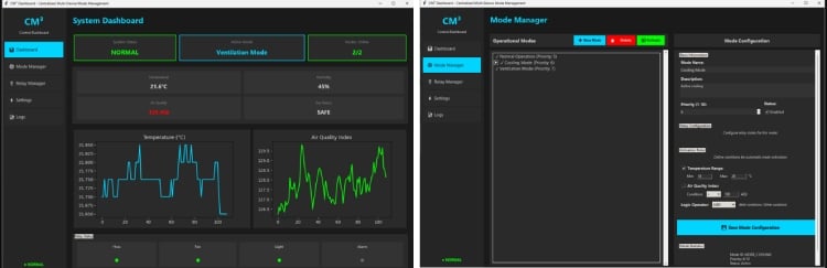
Dashboard Module
The Dashboard gives a real-time overview of the system. It displays:
- System Status (Normal / Warning / Critical)
- Active Operational Mode
- Nodes Online count
• Live sensor values (Temperature, Humidity, AQI, Gas status)
It also includes graphical plots for temperature and air quality trends, enabling users to observe environmental changes over time. Relay indicators provide immediate feedback on device states such as HVAC, Fan, Light, and Alarm.
Mode Manager
The Mode Manager allows users to create, configure, and activate operational modes. Each mode can include:
- Priority level
- Temperature range conditions
- Air quality thresholds
- Logical operators (AND / OR)
- Relay configurations
The system uses priority-based rule evaluation to automatically activate the most appropriate mode when multiple conditions are met.
Relay Manager and Logs
The Relay Manager provides direct visibility and optional manual control of connected relays for testing and maintenance.
The Logs module records system events such as mode transitions, node status changes, and emergency alerts, ensuring traceability and reliability.
Key Features
- Real-time MQTT-based monitoring
- Rule-based mode configuration
- Priority-driven automation
- Modular GUI built using Tkinter
- Clear visual feedback and device state tracking
GitHub Repository


