

There are several critical machines or expensive equipment which suffer damage due to vibrations. In such a case, a vibration sensor is required to find out whether the machine or equipment is producing vibrations or not. Identifying the object which is continuously vibrating is not a tricky job if the proper sensor is used to detect the vibration. There are several types of vibration sensors available in the market, which can detect vibration by sensing acceleration or velocity and could provide excellent results. However, such sensors are too expensive for the accelerometer to be used. An accelerometer is very sensitive and can be used to make an Earthquake detector circuit. However, there are a few dedicated and inexpensive sensors available to detect vibrations only. One such sensor is the SW-420, which we will interface with Arduino Uno. You can Master vibration detection with Arduino using the SW-420 sensor module. When expensive equipment or critical machines suffer damage due to unwanted vibrations, a reliable vibration sensor Arduino system becomes essential for early detection and prevention.
So in this project, a basic vibration sensor module is interfaced with the popular Arduino UNO, and whenever the vibration sensor detects any vibration or jerk, an LED will start blinking.
Table of Contents
Why Choose SW-420 for Arduino Projects?
» Cost-effective: A cheap alternative to expensive accelerometers.
» Easy to connect: Plug and Play with Arduino platforms.
» Adjustable sensitivity: Built-in potentiometer to adjust threshold.
» Digital output: Easy repeated HIGH/LOW processing.
This vibration sensor Arduino project is a great demonstration of how you can build a monitoring system for an LED alert to tell you every time you go above its set threshold.
Key Features of the SW-420 Vibration Sensor
The vibration sensor module for Arduino has the following basic features that make it great for any maker project:
- LM393 Comparator: It produces a clean digital output by comparing the sensor signal against a user-defined reference set point or threshold.
- Sensitivity Potentiometer: a knob that allows the user to fine-tune the vibration detection threshold
- Two LED Indicators: Power LED (red) and output LED (green) for easy monitoring.
- Rugged: The components are mounted on a printed circuit board and will give you reliable operation in a variety of conditions.
Vibration Sensor Arduino Working Principle
Understanding the vibration sensor Arduino working principle is crucial for successful implementation.

This is an SW-420 vibration module, which can work from 3.3V to 5V. The sensor uses an LM393 comparator to detect the vibration over a threshold point and provide digital data, Logic Low or Logic High, 0 or 1. During normal operation, the sensor provides Logic Low, and when the vibration is detected, the sensor provides Logic High. There are three peripherals available in the module: two LEDs, one for the Power state and the other for the sensor’s output. Additionally, a potentiometer is available, which can be further used to control the threshold point of the vibration. In this project, we will use 5V to power the module.
We used the same sensor in the Anti-Theft Alert System using an ATmega8 Microcontroller. Also, a tilt sensor can be used to detect a sudden accident.
Required Components for Vibration Sensor Arduino Project
- Arduino UNO
- SW-420 Vibration Sensor Module
- 5mm LED (Any Colour)
- Jumper Wires(Hookup Wires)
- USB Cable for Uploading Program
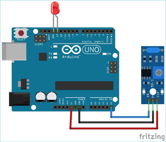
Arduino Vibration Sensor Circuit Diagram & Wiring
The schematic for interfacing the Vibration sensor with Arduino Uno is given below.

The LED is connected to the D13 pin. The module is powered using the available 5V pin in the Arduino. The Ground and the 5V pin are used to power up the Arduino, whereas the A5 pin is used to get the data from the vibration sensor.
The circuit is constructed where the SW-420 module and LED are connected to the Arduino Uno.
Vibration Sensor Arduino Code Implementation
Programming the Arduino UNO to interface with a vibration sensor doesn’t require much effort, as only the input pin should be monitored to make a conclusion. The complete code and working video are attached at the end.
Initially, the Header Files are included. The Arduino header is included since this tutorial was written in Eclipse IDE with the Arduino extension. This sketch will also work for Arduino IDE, and while using this sketch in Arduino IDE, there is no need to include <Arduino.h> header. The following vibration sensor Arduino code demonstrates a complete implementation for detecting vibrations and triggering LED responses.
#include <Arduino.h>
Here, two macros are defined for ON and OFF.
#define ON 1
#define OFF 0
The statement below is used for integrating the LEDs and the Vibration Sensor. The vibration sensor is connected to pin A5. The built-in LED is also used, which is directly connected to the board to pin 13. The 5mm LED is also connected to pin 13.
/*
 * Pin Description
 */
int vibration_Sensor = A5;
int LED = 13;
Two integers are declared, where the sensors present output and the previous output will be stored, which will be further used to detect whether the vibration is happening or not.
/*
 * Programme flow Description
 */
int present_condition = 0;
int previous_condition = 0;
The same pin which is declared as the peripheral connection, the direction of the pins is configured. The sensor pin is an input, and the LED pin is an output.
/*
 * Pin mode setup
 */
void setup() {
            pinMode(vibration_Sensor, INPUT);
            pinMode(LED, OUTPUT);
}
One function is written to blink the LED twice. The delay can be configured by changing the delay value.
void led_blink(void) {
            digitalWrite(LED, ON);
            delay(250);
            digitalWrite(LED, OFF);
            delay(250);
            digitalWrite(LED, ON);
            delay(250);
            digitalWrite(LED, OFF);
            delay(250);
}
In the loop function, the present and previous condition is compared. If these two are not the same, the LEDs start to blink until both are the same. Initially, the two variables hold 0, and the LED remains off during the start of the program. When there is some vibration, the present_condition variable becomes 1 and the LED start to blink. And again, when vibrations stop, both the variables become 0, and the LED stops blinking.
void loop() {
            previous_condition = present_condition;
            present_condition = digitalRead(A5); // Reading digital data from the A5 Pin of the Arduino.
            if (previous_condition != present_condition) {
                       led_blink();
            } else {
                       digitalWrite(LED, OFF);
            }
}
This finishes the programming of the Arduino UNO with the Vibration sensor. The final step will be testing the whole setup.
Testing the Arduino Vibration Sensor Circuit
The circuit doesn’t require an additional breadboard. It can be simply tested using the Arduino UNO Board. The LED is monitored when the vibration sensor is hit or if it changes its state. The LED will blink when connected to Pin 13 of Arduino UNO when there are some vibrations. If the vibration sensor doesn’t work, then please check the connection and power. Avoid any loose connections between the sensor and the microcontroller.
Troubleshooting Guide for Arduino Vibration Sensor Issues
| Problem | Possible Cause | Solution |
| LED doesn't blink on vibration | Loose connections or incorrect wiring | Check all connections, verify pin assignments in code |
| Sensor too sensitive (false triggers) | Sensitivity set too high | Rotate potentiometer clockwise to reduce sensitivity |
| Sensor not responsive | Sensitivity set too low | Rotate potentiometer counter-clockwise to increase sensitivity |
| Power LED not illuminated | No power supply or faulty module | Check 5V connection, verify Arduino power supply |
| Erratic behavior | Electrical interference or poor grounding | Improve ground connections, use shielded cables if necessary |
Technical Summary and GitHub Repository
A short Technical Summary gives you the basics, and our GitHub Repository provides everything you need to build and adapt the project.


Real-World Applications for Arduino Vibration Sensor Systems
The versatility of vibration sensor Arduino systems makes them suitable for numerous practical applications across different industries and projects.
| Application Category | Specific Use Cases | Benefits |
| Security Systems | Door/window intrusion detection, Safe monitoring, Perimeter security | Cost-effective security, Easy installation, Battery operation possible |
| Equipment Monitoring | Motor vibration analysis, Pump condition monitoring, HVAC system surveillance | Predictive maintenance, Reduced downtime, Early fault detection |
| Automotive Projects | Vehicle theft detection, Accident monitoring, Engine diagnostics | Enhanced vehicle security, Accident response, Maintenance alerts |
| Home Automation | Washing machine cycle detection, Appliance monitoring, Smart home integration | Automated notifications, Energy monitoring, Convenience features |
So this is how a Vibration sensor can be interfaced with Arduino UNO. If you have any doubts or suggestions, then you can reach us through the forum, or you can also comment below.
Frequently Asked Questions about the Vibration Sensor Arduino
⇥ 1. How will the SW-420 vibration sensor work with Arduino?
The SW-420 has an internal spring-mass system that creates electrical signals when vibrations occur. The LM393 comparator converts these analog signals into digital HIGH/LOW signal outputs that can be read by Arduino through digital pins - one fairly simple way to detect vibrations.
⇥ 2. What is the difference between SW-420 and accelerometer sensors?
The SW-420 provides simple digital vibration detection (present/absent) and can be found for less than $5, while accelerometers provide accurate acceleration values along more than one axes, starting in the $20-$50+ range. The SW-420 is best suited for simple detection applications and accelerometers for high-level motion analysis.
⇥ 3. Can I make the SW-420 vibration sensor more or less sensitive?
Yes, the SW-420 has an onboard potentiometer that is used to adjust sensitivity. If turned clockwise, the sensitivity is lowered (fewer false triggers), and if turned counter-clockwise, the sensitivity increases (to sense smaller vibrations). As with any potentiometer, adjust to your needs - based on your particular application needs.
⇥ 4. Which Arduino pins should I connect SW-420 to?
The SW-420 digital output can be wired to any of the Arduino digital pins (D2-D13) or analog pins configured to run as digital input (A0-A5). Do not wire to D0/D1 (used to communicate serially) and pin D13, in case you want to view signals more easily while debugging with the internal LED.
⇥ 5. Why do I get a false positive from my vibration sensor?
False positives are more often than not caused by too sensitive a setting, interference, loose connections, or environmental vibration. Fix: check to make sure all connections are tight, have a ground, and make sure you are not leaving it near a motor, transformer, or other source of interference.
⇥ 6. Will SW-420 work with 3.3V Arduino boards like ESP32.
Yes! SW-420 operates between 3.3V and 5V, which means it will be fine with ESP32, Arduino Pro Mini 3.3V and all other 3.3V or low voltage boards. The digital output levels are 3.3V logic compatible for equal functionality across all of your Arduino boards.
Projects using Sensor Module
Previously, we have used this Sensor Module to build many interesting projects. If you want to know more about those topics, links are given below.

Interfacing the Hall Effect Sensor Module with Arduino
This tutorial will show how we can interface the Hall effect sensor with Arduino. The module we are going to use can be operated in either analog mode or digital output mode. We will monitor the module’s output and will change the Arduino onboard LED state according to it.

How to Interface Arduino with NEO 6M GPS Module?
From the important parts of the GPS module to the pinout interfacing and coding, you can find everything about the Arduino GPS sensor in this article. Arduino tutorial. Also, if you are trying to build a GPS tracker using this NEO 6M GPS module, then do check out our Arduino GPS Tracker Project for instructions on how to build one.

How Does the GP2Y1014AU0F Dust Sensor Work and How to Interface it with Arduino?
In this article, we are going to interface the GP2Y1014AU0F Dust Sensor with Arduino to add basic particle sensing to our project. But let's be real, this sensor is not as good as the Nova SDS110 Sensor, which can measure PM2.5 and PM10 in the air. However, for the price of only 5$ or approximately 400Rs, it can't be beaten. This comprehensive tutorial covers interfacing the GP2Y1014AU0F dust sensor with Arduino, including detailed pinout diagrams, programming code, and practical projects.
Complete Project Code
/*//==============================================================================//
 * Vibration Sensor interfacing with Arduino
 * Date: - 15-04-2019
 * Author:- Sourav Gupta
 * For:- circuitdigest.com
 */ //=============================================================================//
#include <Arduino.h>
#include <stdio.h>

#define ON 1
#define OFF 0

/*
 * Pin Description
 */
int vibration_Sensor = A5;
int LED = 13;

/*
 * Programme flow Description
 */
int present_condition = 0;
int previous_condition = 0;

/*
 * Pin mode setup
 */
void setup() {
pinMode(vibration_Sensor, INPUT);
pinMode(LED, OUTPUT);
}

/*
 * Led blink
 */
void led_blink(void);

/*
 * main_loop
 */

void loop() {
previous_condition = present_condition;
present_condition = digitalRead(A5); // Reading digital data from the A5 Pin of the Arduino.

if (previous_condition != present_condition) {
led_blink();

} else {
digitalWrite(LED, OFF);
}
}

void led_blink(void) {
digitalWrite(LED, ON);
delay(250);
digitalWrite(LED, OFF);
delay(250);
digitalWrite(LED, ON);
delay(250);
digitalWrite(LED, OFF);
delay(250);
}

I am trying to find the symbol of the SW 420 in the fritzing software but I cannot find it. Can you tell me what the name of it is in the software?