
The OS present inside the embedded devices is called an RTOS (Real-Time Operating System). In embedded devices, real-time tasks are critical where timing plays a very important role. Real-time tasks are Time Deterministic means the response time to any event is always constant so that it can be guaranteed that any particular event will occur at a fixed time. RTOS is designed to run applications with very precise timing and a high degree of reliability. RTOS also helps in multi-tasking with a single core.
We already covered a tutorial on how to use RTOS in embedded systems where you can know more about RTOS, the difference between general-purpose OS and RTOS, different types of RTOS, etc.
In this tutorial, we will start with FreeRTOS. FreeRTOS is a class of RTOS for embedded devices which is small enough to be run on 8/16-bit microcontrollers, although its use is not limited to these microcontrollers. It is a completely open-source and it’s code is available on github. If we know some basic concepts of RTOS, then it is very easy to use FreeRTOS because it has well-documented APIs which can be directly used in the code without knowing the backend part of the coding. Complete FreeRTOS documentation can be found here.
As FreeRTOS can run on 8-bit MCU so it can also be run on Arduino Uno board. We have to just download the FreeRTOS library and then start implementing the code using APIs. This tutorial is meant for a complete beginner, below are the topics, we will cover in this Arduino FreeRTOS tutorial:
- How RTOS works
- Some frequently used terms in RTOS
- Installing FreeRTOS in Arduino IDE
- How to create FreeRTOS Tasks with example
How RTOS works?
Before starting with RTOS working, let’s see what is a Task. Task is a piece of code that is schedulable on the CPU to execute. So, if you want to perform some task, then it should be scheduled using kernel delay or using interrupts. This work is done by Scheduler present in the kernel. In a single-core processor, the scheduler helps tasks to execute in a particular time slice but it seems like different tasks are executing simultaneously. Every task runs according to the priority given to it.
Now, let’s see what happens in the RTOS kernel if we want to create a task for LED blinking with a one-second interval and put this task on the highest priority.
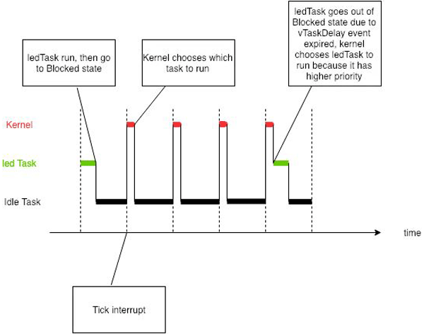
Apart from the LED task, there will be one more task which is created by the kernel, it is known as an idle task. The idle task is created when no task is available for execution. This task always runs on the lowest priority i.e. 0 priority. If we analyze the timing graph given above, it can be seen that execution starts with an LED task and it runs for a specified time then for remaining time, the idle task runs until a tick interrupt occurs. Then kernel decides which task has to be executed according to the priority of the task and total elapsed time of the LED task. When 1 second is completed, the kernel chooses the led task again to execute because it has a higher priority than the idle task, we can also say that the LED task preempts the idle task. If there are more than two tasks with the same priority then they will run in round-robin fashion for a specified time.
Below the state diagram as it shows the switching of the non-running task into running state.
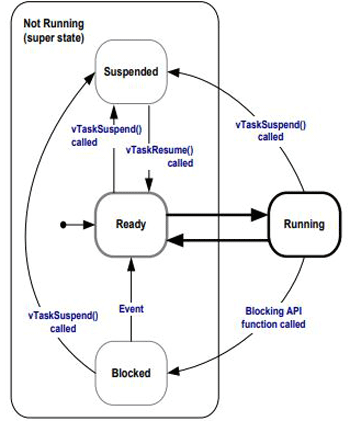
Every newly created task goes in Ready state (part of not running state). If the created task (Task1) has the highest priority than other tasks, then it will move to running state. If this running task preempts by the other task, then it will go back to the ready state again. Else if task1 is blocked by using blocking API, then CPU will not engage with this task until the timeout defined by the user.
If Task1 is suspended in running state using Suspend APIs, then Task1 will go to Suspended state and it is not available to the scheduler again. If you resume Task1 in the suspended state then it will go back to the ready state as you can see in the block diagram.
This is the basic idea of how Tasks run and change their states. In this tutorial, we will implement two tasks in Arduino Uno using FreeRTOS API.
Frequently used terms in RTOS
1. Task: It is a piece of code that is schedulable on the CPU to execute.
2. Scheduler: It is responsible for selecting a task from the ready state list to the running state. Schedulers are often implemented so they keep all computer resources busy (as in load balancing).
3. Preemption: It is the act of temporarily interrupting an already executing task with the intention of removing it from the running state without its co-operation.
4. Context Switching: In priority-based preemption, the scheduler compares the priority of running tasks with a priority of ready task list on every systick interrupt. If there is any task in the list whose priority is higher than running task then context switch occurs. Basically, in this process contents of different tasks get saved in their respective stack memory.
5. Types of Scheduling policies:
- Preemptive Scheduling: In this type of scheduling, tasks run with equal time slice without considering the priorities.
- Priority-based Preemptive: High priority task will run first.
- Co-operative Scheduling: Context switching will happen only with the co-operation of running tasks. Task will run continuously until task yield is called.
6. Kernel Objects: For signaling the task to perform some work, the synchronization process is used. To perform this process Kernel objects are used. Some Kernel objects are Events, Semaphores, Queues, Mutex, Mailboxes, etc. We will see how to use these objects in upcoming tutorials.
From the above discussion, we have got some basic ideas about the RTOS concept and now we can implement the FreeRTOS project in Arduino. So, let's get started by installing FreeRTOS libraries in Arduino IDE.
Installing Arduino FreeRTOS Library
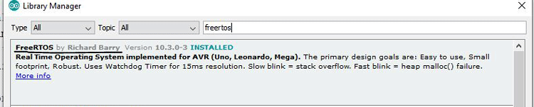
1. Open Arduino IDE and go to Sketch -> Include Library -> Manage Libraries. Search for FreeRTOS and install the library as shown below.
You can download the library from github and Add the .zip file in Sketch-> Include Library -> Add .zip file.
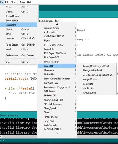
Now, restart the Arduino IDE. This library provides some example code, also that can be found in File -> Examples -> FreeRTOS as shown below.
Here we will write the code from scratch to understand the working, later you can check the example codes and use them.
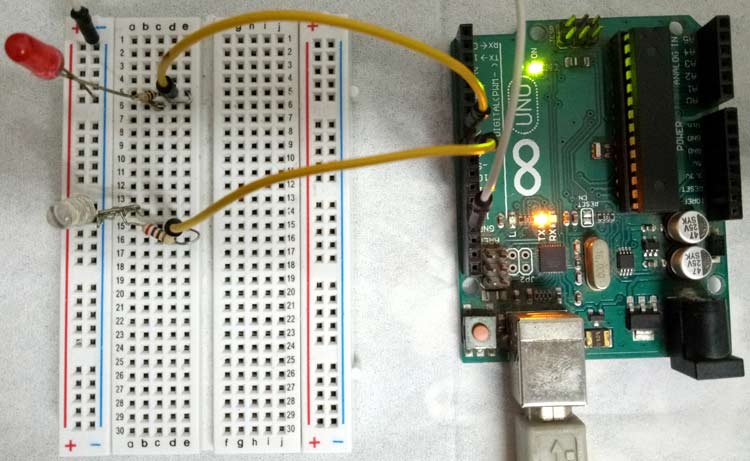
Circuit Diagram
Below is the circuit diagram for creating Blinking LED task using FreeRTOS on Arduino:

Arduino FreeRTOS Example- Creating FreeRTOS tasks in Arduino IDE
Let’s see a basic structure to write a FreeRTOS project.
1. First, include Arduino FreeRTOS header file as
#include <Arduino_FreeRTOS.h>
2. Give the function prototype of all functions that you are writing for execution which is written as
void Task1( void *pvParameters );
void Task2( void *pvParameters );
..
….
3. Now, in void setup() function, create tasks and start the task scheduler.
For creating task, xTaskCreate() API is called in setup function with certain parameters/arguments.
xTaskCreate( TaskFunction_t pvTaskCode, const char * const pcName, uint16_t usStackDepth, void *pvParameters, UBaseType_t uxPriority, TaskHandle_t *pxCreatedTask );
There are 6 arguments that should be passed while creating any task. Let’s see what these arguments are
- pvTaskCode: It is simply a pointer to the function that implements the task (in effect, just the name of the function).
- pcName: A descriptive name for the task. This is not used by FreeRTOS. It is included purely for debugging purposes.
- usStackDepth: Each task has its own unique stack that is allocated by the kernel to the task when the task is created. The value specifies the number of words the stack can hold, not the number of bytes. For example, if the stack is 32-bits wide and usStackDepth is passed in as 100, then 400 bytes of stack space will be allocated (100 * 4 bytes) in RAM. Use this wisely because Arduino Uno has only 2Kbytes of RAM.
- pvParameters: Task input parameter (can be NULL).
- uxPriority: Priority of the task ( 0 is the lowest priority).
- pxCreatedTask: It can be used to pass out a handle to the task being created. This handle can then be used to reference the task in API calls that, for example, change the task priority or delete the task (can be NULL).
Example of task creation
xTaskCreate(task1,"task1",128,NULL,1,NULL);
 xTaskCreate(task2,"task2",128,NULL,2,NULL);
Here, Task2 has higher priority and hence executes first.
4. After creating the task, start the scheduler in a void setup using vTaskStartScheduler(); API.
5. Void loop() function will remain empty as we don’t want to run any task manually and infinitely. Because task execution is now handled by Scheduler.
6. Now, we have to implement task functions and write the logic that you want to execute inside these functions. The function name should be the same as the first argument of xTaskCreate() API.
void task1(void *pvParameters)
{
while(1) {
..
..//your logic
}
}
7. Most of the code needs delay function to stop the running task but in RTOS it is not suggested to use Delay() function as it stops the CPU and hence RTOS also stops working. So FreeRTOS has a kernel API to block the task for a specific time.
vTaskDelay( const TickType_t xTicksToDelay );
This API can be used for delay purposes. This API delay a task for a given number of ticks. The actual time for which the task remains blocked depends on the tick rate. The constant portTICK_PERIOD_MS can be used to calculate real-time from the tick rate.
This means if you want a delay of 200ms, just write this line
vTaskDelay( 200 / portTICK_PERIOD_MS );
So for this tutorial, we will use these FreeRTOS APIs to implement three tasks.
APIs to be used:
- xTaskCreate();
- vTaskStartScheduler();
- vTaskDelay();
Task to be created for this tutorial:
- LED blink at Digital pin 8 with 200ms frequency
- LED blink at Digital pin 7 with 300ms frequency
- Print numbers in serial monitor with 500ms frequency.
FreeRTOS Task Implementation in Arduino IDE
1. From the above basic structure explanation, include the Arduino FreeRTOS header file. Then make function prototypes. As we have three tasks, so make three functions and it’s prototypes.
#include <Arduino_FreeRTOS.h>
void TaskBlink1( void *pvParameters );
void TaskBlink2( void *pvParameters );
void Taskprint( void *pvParameters );
2. In void setup() function, initialize serial communication at 9600 bits per second and create all three tasks using xTaskCreate() API. Initially, make the priorities of all tasks as ‘1’ and start the scheduler.
void setup() {
Serial.begin(9600);
xTaskCreate(TaskBlink1,"Task1",128,NULL,1,NULL);
xTaskCreate(TaskBlink2,"Task2 ",128,NULL,1,NULL);
xTaskCreate(Taskprint,"Task3",128,NULL,1,NULL);
vTaskStartScheduler();
}
3. Now, implement all three functions as shown below for task1 LED blink.
void TaskBlink1(void *pvParameters)
{
pinMode(8, OUTPUT);
while(1)
{
digitalWrite(8, HIGH);
vTaskDelay( 200 / portTICK_PERIOD_MS );
digitalWrite(8, LOW);
vTaskDelay( 200 / portTICK_PERIOD_MS );
}
}
Similarly, implement TaskBlink2 function. Task3 function will be written as
void Taskprint(void *pvParameters)
{
int counter = 0;
while(1)
{
counter++;
Serial.println(counter);
vTaskDelay( 500 / portTICK_PERIOD_MS );
}
}
That’s it. We have successfully completed a FreeRTOS Arduino project for Arduino Uno. You can find full code along with a video at the end of this tutorial.
Finally, connect two LEDs at the digital pin 7 and 8 and upload the code on your Arduino board and open the Serial monitor. You will see a counter is running once in 500ms with task name as shown below.
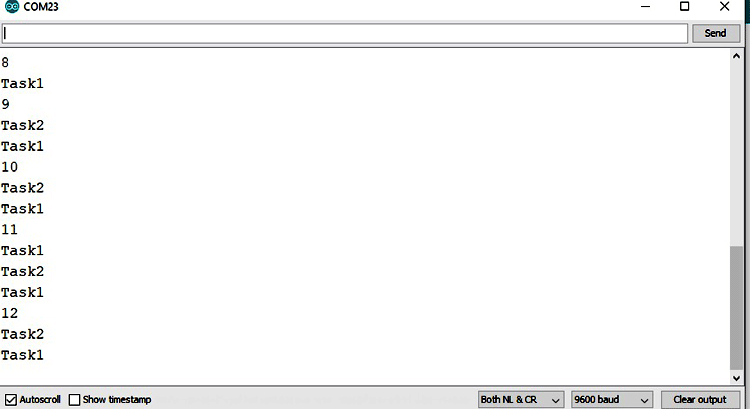
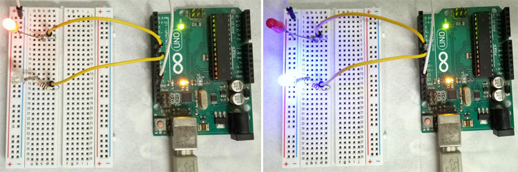
Also, observe the LEDs, they are blinking at different time intervals. Try to play with the priority argument in the xTaskCreate function. Change the number and observe the behavior on serial monitor and LEDs.
Now, you can understand the first two example codes in which analog read and digital read tasks are created. In this way, you can make more advance projects using just Arduino Uno and FreeRTOS APIs.
Complete Project Code
#include <Arduino_FreeRTOS.h>

void TaskBlink1( void *pvParameters );

void TaskBlink2( void *pvParameters );

void Taskprint( void *pvParameters );

void setup() {

  // initialize serial communication at 9600 bits per second:

  Serial.begin(9600);

  xTaskCreate(

    TaskBlink1

    ,  "task1"

    ,  128

    ,  NULL

    ,  1

    ,  NULL );

  xTaskCreate(

    TaskBlink2

    ,  "task2"

    ,  128

    ,  NULL

    ,  1

    ,  NULL );

    xTaskCreate(

    Taskprint

    ,  "task3"

    ,  128

    ,  NULL

    ,  1

    ,  NULL );

vTaskStartScheduler();

}

void loop()

{

}

void TaskBlink1(void *pvParameters)  {

  pinMode(8, OUTPUT);

  while(1)

  {

    Serial.println("Task1");

    digitalWrite(8, HIGH);

    vTaskDelay( 200 / portTICK_PERIOD_MS );

    digitalWrite(8, LOW);

    vTaskDelay( 200 / portTICK_PERIOD_MS );

  }

}

void TaskBlink2(void *pvParameters)

{

  pinMode(7, OUTPUT);

  while(1)

  {

    Serial.println("Task2");

    digitalWrite(7, HIGH);

    vTaskDelay( 300 / portTICK_PERIOD_MS );

    digitalWrite(7, LOW);

    vTaskDelay( 300 / portTICK_PERIOD_MS );

  }

}

void Taskprint(void *pvParameters)  {

  int counter = 0;

  while(1)

  {

counter++;

  Serial.println(counter);

  vTaskDelay(500 / portTICK_PERIOD_MS);    }

}
