
In the previous tutorial, we introduced FreeRTOS in Arduino Uno and created a task for the blinking LED. Now, in this tutorial, we will dive more into advance concepts of RTOS APIs and learn about communication between different tasks. Here we also learn about Queue to transfer data from one task to another and demonstrate the working of queue APIs by interfacing 16x2 LCD and LDR with the Arduino Uno.
Before discussing about Queues, let’s see one more FreeRTOS API which is helpful in deleting the tasks when it is finished with the assigned work. Sometimes the task needs to be deleted to free the allotted memory. In continuation of the previous tutorial, we will use vTaskDelete() API function in the same code to delete one of the tasks. A task can use the vTaskDelete() API function to delete itself, or any other task.
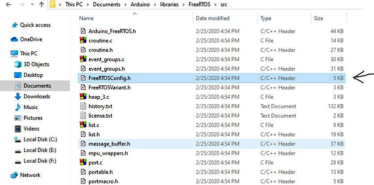
To use this API, you have to configure the FreeRTOSConfig.h file. This file is used to tailor FreeRTOS according to the application. It is used to change the scheduling algorithms and many other parameters. The file can be found in the Arduino Directory which is generally available in the Documents folder of your PC. In my case, it is available in \Documents\Arduino\libraries\FreeRTOS\src as shown below.
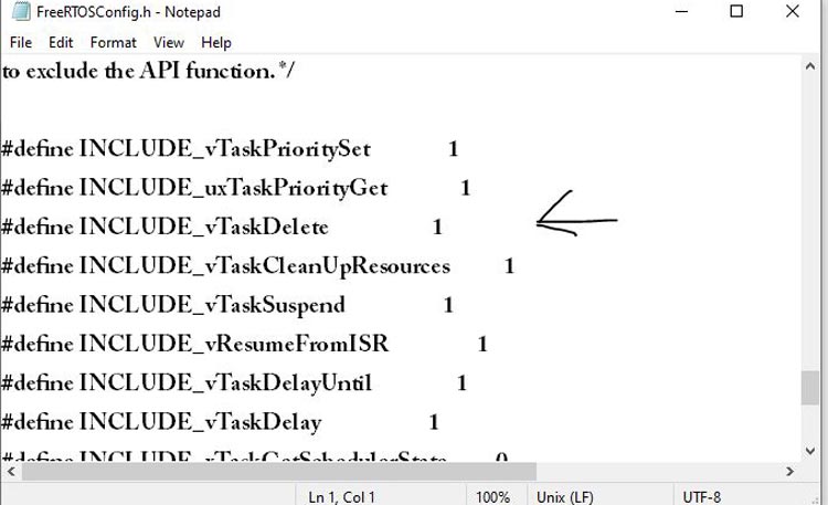
Now, open this file using any text editor and search for the #define INCLUDE_vTaskDelete and make sure its value is ‘1’ (1 means enable and 0 means disable). It is 1 by default but checks for it.
We will be using this config file frequently in our next tutorials for setting the parameters.
Now, let’s see how to delete a task.
Deleting a Task in FreeRTOS Arduino
To delete a task, we have to use the vTaskDelete() API function. It takes only one argument.
vTaskDelete( TaskHandle_t pxTaskToDelete );
pxTaskToDelete: It is the handle of the task that is to be deleted. It is the same as the 6th argument of xTaskCreate() API. In the previous tutorial, this argument is set as NULL but you can pass the address of the contents of the task by using any name. Let say if you want to set task handle for Task2 which is declared as
TaskHandle_t any_name;
Example: TaskHandle_t xTask2Handle;
Now, in vTaskCreate() API set 6th argument as
xTaskCreate(TaskBlink2 , "task2" , 128 , NULL, 1 , &xTask2Handle );
The content of this task can be now accessed using the handle given by you.
Also, a task can delete itself by passing NULL in place of a valid task handle.
If we want to delete Task 3 from task 3 itself, you need to write vTaskDelete( NULL ); inside the Task3 function but if you want to delete task 3 from task 2 then write vTaskDelete(xTask3Handle ); inside the task2 function.
In previous tutorial code, to delete Task2 from task2 itself, just add vTaskDelete(NULL); in void TaskBlink2(void *pvParameters) function. Then the above function will look like this
void TaskBlink2(void *pvParameters)
{
Serial.println(“Task2 is running and about to delete”);
vTaskDelete(NULL);
pinMode(7, OUTPUT);
while(1)
{
digitalWrite(7, HIGH);
vTaskDelay( 300 / portTICK_PERIOD_MS );
digitalWrite(7, LOW);
vTaskDelay( 300 / portTICK_PERIOD_MS );
}
}
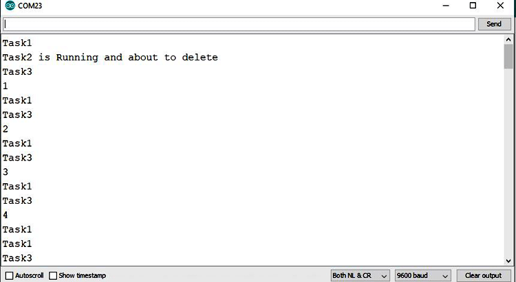
Now, upload the code and observe the LEDs and Serial monitor. You will see that the second LED is not blinking now and task2 is deleted after encountering the delete API.
So this API can be used to stop the execution of the particular task.
Now, let’s start with the Queue.
What is the Queue in FreeRTOS?
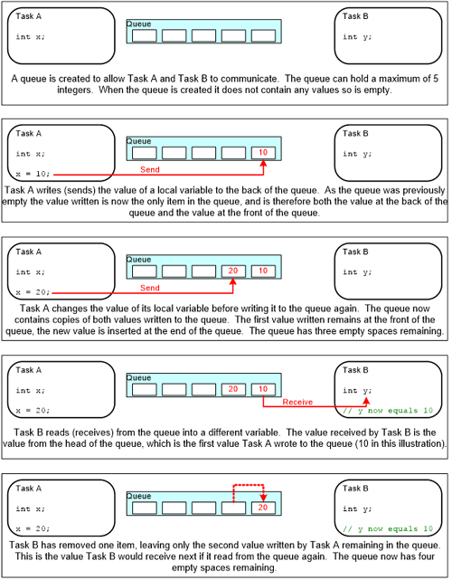
Queue is the data structure that can hold the finite number of fixed size elements and it is operated in the FIFO scheme (First-in First-out). Queues provide a task-to-task, task-to-interrupt, and interrupt-to-task communication mechanism.
The maximum number of elements queue can hold is called its “length”. Both the length and the size of each element are set when the queue is created.
An example of how the queue is used for data transfer is illustrated well in FreeRTOS documentation that can be found here. You can easily understand the given example.
After understanding the Queues, let’s try to understand the process of creating a queue and try to implement it in our FreeRTOS code.
Creating a Queue in FreeRTOS
First, describe the problem statement that is to be implemented with the help of the FreeRTOS queue and Arduino Uno.
We want to print the value of the LDR sensor on 16*2 LCD. So there are two tasks now
- Task1 is getting analog values of LDR.
- Task2 is printing the analog value on LCD.
So, here queue plays its role because to send the data generated by task1 to task2. In task1, we will send analog value to the queue and in task2, we will receive it from the queue.
There are three functions to work with queues
- Creating a Queue
- Sending data to Queue
- Receiving data from Queue
For creating queue, use xQueueCreate() function API. It takes two arguments.
xQueueCreate( UBaseType_t uxQueueLength, UBaseType_t uxItemSize );
uxQueueLength: The maximum number of items that the queue being created can hold at any one time.
uxItemSize: The size in bytes of each data item that can be stored in the queue.
If this function returns NULL then the queue is not created due to insufficient memory and if it returns a non-NULL value, the queue is created successfully. Store this return value to a variable to use it as a handle to access the queue as shown below.
QueueHandle_t queue1;
queue1 = xQueueCreate(4,sizeof(int));
This will create a 4 element queue in heap memory of int size (2 bytes of each block) and store the return value to the queue1 handle variable.
2. Sending Data to Queue in FreeRTOS
To send the values to the queue, FreeRTOS has 2 variants of API for this purpose.
- xQueueSendToBack(): Used to send data to the back (tail) of a queue.
- xQueueSendToFront(): Used to send data to the front (head) of a queue.
Now, xQueueSend() is equivalent to, and exactly the same as, xQueueSendToBack().
All these APIs takes 3 arguments.
xQueueSendToBack( QueueHandle_t xQueue, const void * pvItemToQueue, TickType_t xTicksToWait );
xQueue: The handle of the queue to which the data is being sent (written). This variable is the same as used to store the return value of xQueueCreate API.
pvItemToQueue: A pointer to the data to be copied into the queue.
xTicksToWait: The maximum amount of time the task should remain in the Blocked state to wait for space to become available in the queue.
Setting xTicksToWait to portMAX_DELAY will cause the task to wait indefinitely (without timing out), provided INCLUDE_vTaskSuspend is set to 1 in FreeRTOSConfig.h else you can use the macro pdMS_TO_TICKS() to convert a time specified in milliseconds into a time specified in ticks.
3. Receiving Data from Queue in FreeRTOS
To receive (read) an item from a queue, xQueueReceive() is used. The item that is received is removed from the queue.
This API also takes three arguments.
xQueueReceive( QueueHandle_t xQueue, void * const pvBuffer, TickType_t xTicksToWait );
First and third arguments are the same as sending API. Only the second argument is different.
const pvBuffer: A pointer to the memory into which the received data will be copied.
Hope you understood the three APIs. Now, we will implement these APIs in the Arduino IDE and try to solve the problem statement that we have described above.
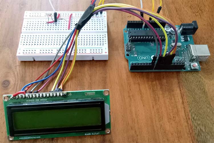
Circuit Diagram

This is how it looks on the breadboard:
Implementing FreeRTOS Queue in Arduino IDE
Let’s start writing code for our application.
1. First, open Arduino IDE and include the Arduino_FreeRTOS.h header file. Now, if any kernel object like queue is used then include the header file of it. As we are using 16*2 LCD so include the library for it also.
#include <Arduino_FreeRTOS.h>
#include <queue.h>
#include <LiquidCrystal.h>
2. Initialize a queue handle to store the contents of the queue. Also, initialize LCD pin numbers.
QueueHandle_t queue_1;
LiquidCrystal lcd(7, 8, 9, 10, 11, 12);
3. In void setup(), initialize LCD and serial monitor with 9600 baud rate. Create a queue and two tasks using the respective APIs. Here we will create a queue of size 4 with integer type. Create a task with equal priorities and later on try to play with this number. Finally, start the scheduler as shown below.
void setup() {
Serial.begin(9600);
lcd.begin(16, 2);
queue_1 = xQueueCreate(4, sizeof(int));
if (queue_1 == NULL) {
Serial.println("Queue can not be created");
}
xTaskCreate(TaskDisplay, "Display_task", 128, NULL, 1, NULL);
xTaskCreate(TaskLDR, "LDR_task", 128, NULL, 1, NULL);
vTaskStartScheduler();
}
4. Now, make two functions TaskDisplay and TaskLDR. In TaskLDR function, read analog pin A0 in a variable as we have LDR connected to the A0 pin of Arduino UNO. Now send the value stored in the variable by passing it in the xQueueSend API and send the task to block state after 1 second using vTaskDelay() API as shown below.
void TaskLDR(void * pvParameters) {
int current_intensity;
while(1) {
Serial.println("Task1");
current_intensity = analogRead(A0);
Serial.println(current_intensity);
xQueueSend(queue_1, ¤t_intensity, portMAX_DELAY);
vTaskDelay( 1000 / portTICK_PERIOD_MS );
}
}
5. Similarly, make a function for TaskDisplay and receive the values in a variable that is passed to the xQueueReceive function. Also, xQueueReceive() returns pdPASS if the data can be received successfully from the queue and returns errQUEUE_EMPTY if a queue is empty.
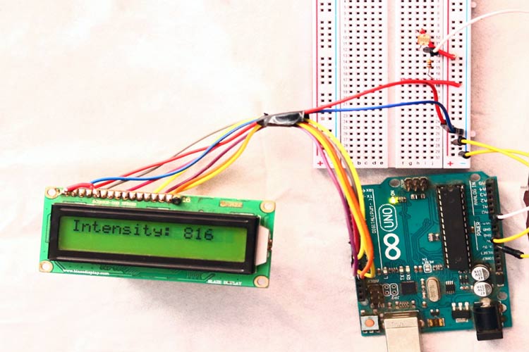
Now, display the values to the LCD using lcd.print() function.
void TaskDisplay(void * pvParameters) {
int intensity = 0;
while(1) {
Serial.println("Task2");
if (xQueueReceive(queue_1, &intensity, portMAX_DELAY) == pdPASS) {
lcd.clear();
lcd.setCursor(0, 0);
lcd.print("Intensity:");
lcd.setCursor(11, 0);
lcd.print(intensity);
}
}
}
That’s it. We have finished the coding part of Queue implementation. Complete code with a working Video can be found at the end.
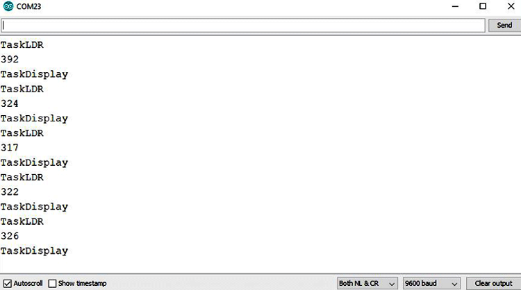
Now, connect the LCD and LDR with Arduino UNO according to the circuit diagram upload the code. Open the serial monitor and observe the tasks. You will see tasks are switching and LDR values are changing according to the light intensity.
NOTE: Most of the libraries made for different sensors are not supported by the FreeRTOS kernel due to delay function implementation inside the libraries. Delay makes the CPU stop completely, therefore, the FreeRTOS kernel also stops working and code will not execute further and it starts misbehaving. So, we have to make the libraries delay-free to work with the FreeRTOS.
Complete Project Code
#include <Arduino_FreeRTOS.h>
#include <queue.h>
#include <LiquidCrystal.h>
QueueHandle_t queue_1;
LiquidCrystal lcd(7, 8, 9, 10, 11, 12); // RST E D4 D5 D6 D7
void setup() {
Serial.begin(9600);
lcd.begin(16, 2);
queue_1 = xQueueCreate(5, sizeof(int));
if (queue_1 == NULL) {
Serial.println("Queue can not be created");
}
xTaskCreate(TaskDisplay, "Display_task", 128, NULL, 1, NULL);
xTaskCreate(TaskLDR, "LDR_task", 128, NULL, 1, NULL);
vTaskStartScheduler();
}
void loop() {
}
void TaskDisplay(void * pvParameters) {
int intensity = 0;
while(1) {
Serial.println("TaskDisplay");
if (xQueueReceive(queue_1, &intensity, portMAX_DELAY) == pdPASS) {
lcd.clear();
lcd.setCursor(0, 0);
lcd.print("Intensity:");
lcd.setCursor(11, 0);
lcd.print(intensity);
}
}
}
void TaskLDR(void * pvParameters) {
int current_intensity;
while(1) {
Serial.println("TaskLDR");
current_intensity = analogRead(A0);
Serial.println(current_intensity);
xQueueSend(queue_1, ¤t_intensity, portMAX_DELAY);
vTaskDelay( 1000 / portTICK_PERIOD_MS );
}
}
