

Smart speakers like Amazon Echo or Google home are getting popular now days and both have capability to integrate custom skill or action to control any appliance using those Smart speaker. We previously built our own Smart speaker using Raspberry Pi and Alexa, and also controlled home appliances using this Raspberry Pi smart speaker.
Home automation has become very common now days and people are using IoT to automate everything in their home. Here in this tutorial we will use a Real Amazon Echo dot speaker and create a custom skill to control AC home appliances like lights, Fans, TVs, Sockets using an Amazon Echo dot Speaker. Here we will use Arduino UNO and an ESP8266-01 Wi-Fi module to connect Echo dot speaker with AC appliances. After this tutorial, you will be able to control any appliance though Alexa.
Hardware Components Used:
- Arduino UNO
- ESP-01 Module
- Amazon Alexa echo dot
- CP2102 USB-TTL Converter
- Breadboard
- 5V Relay Module
- AC Appliances
- Jumpers
Programming ESP-01 Module using CP2102 USB-TTL Converter:
Here ESP-01 is programmed using a CP2102 USB-TTL converter; it can also be programmed using an Arduino UNO board. Here in my case, I have used a CP2102 module and the steps for doing this are explained below.
ESP-01 Module
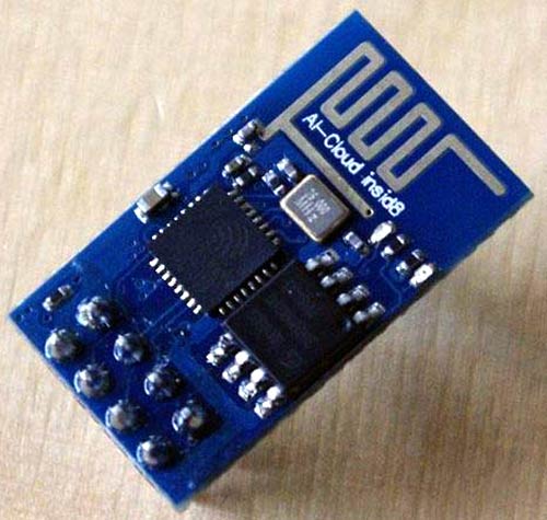
The ESP8266 ESP-01 is a Wi-Fi module that is very popular in designing IoT applications and it is used to allow microcontrollers like Arduino UNO to connect with the internet. This module is a self-contained system on a chip (SOC) that can act like a small computer. It comes with a pre-installed AT firmware, hence we can program it using Arduino IDE. You can learn more about the ESP-01 Wi-Fi transceiver and its programming using Arduino IDE by following the link.
Pin description:
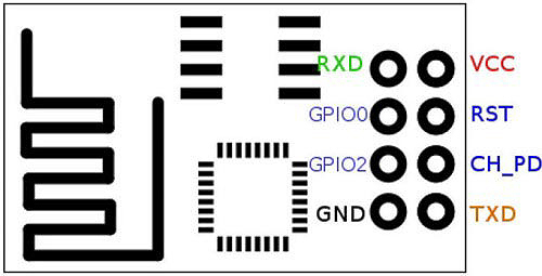
VCC: Power supply pin of ESP-01 which can be supplied with 3.3V DC
GND: Ground reference pin of ESP-01
TXD: Used as UART Transmitter pin
RXD: Used as UART Receiver Pin
RESET: It is used to reset the Module and it is an active LOW pin.
CH_PD: It is the chip enable pin which is an active HIGH pin.
GPIO0: This pin serves two purposes. One is as General purpose Input/output and other is to enable Programming mode of ESP-01
GPIO2: This is a General purpose Input/output pin.
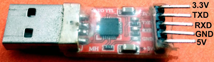
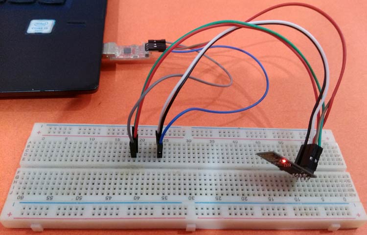
Connection of ESP-01 with CP2102 module:
The figure below shows the pinout diagram of a CP2102 USB-TTL converter. Connect the ESP-01 module with the CP2102 USB-TTL converter module as per the table below.
ESP-01 Module | CP2102 Module |
VCC | 3.3V |
GND | GND |
RXD | TXD |
TXD | RXD |
CH_PD | 3.3V |
RESET | No connection |
GPIO0 | GND |
GPIO2 | No connection |
After successful completion of the connection above, the circuit should look something like below:
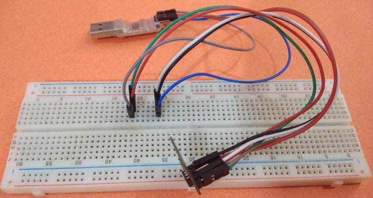
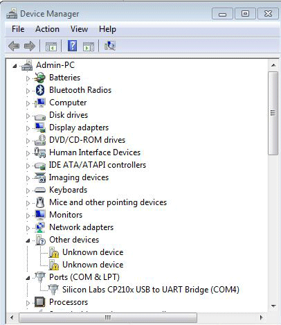
Then connect the CP2102 Module to our PC for programming. Before uploading the code to ESP-01, first, check for the communication port. For this go to start-> and search for device manager. Then click on COMs and Ports. Under this option we should be getting a COM Port with a USB-TTL converter name like “Silicon labs CP21xx USB-UART Bridge” as shown in the image below:
After successful completion of the above steps, Open Arduino IDE and select the board as “Generic ESP8266 Module” from Tools menu and select the COM port which we got in the previous stage.
Programming of ESP-01 Module for Alexa Home Automation
Complete code is given at the end of this project. Here is the stepwise explanation of the code which is to be uploaded on the ESP-01 module. The first step is to include all the necessary libraries. You can download the “fauxmoESP.h” library from the link here.
#include <Arduino.h>
#include <ESP8266WiFi.h>
#include "fauxmoESP.h"
In this step, we have to define all the credentials which are required to connect ESP-01 with the internet. Update your network SSID and password data in the program.
#define SSID "*******"
#define pass "*******"
Next define the name of the devices, which we need to control from Alexa. In my case, I have taken my device names as "bedroom light”, “bedroom fan" and "smart socket."
#define device1 "bedroom light"
#define device2 "bedroom fan"
#define device3 "smart socket"
The function WiFi.mode is used to set up the ESP-01 module as Station mode and the function WiFi.begin is used to connect the ESP-01 Module to the internet which takes the network’s SSID and password as its arguments.
WiFi.mode(WIFI_STA);
WiFi.begin(ssid,pass);
The next part is to initialize all the functions of the Fauxmo class like create the server, enable the port number for Alexa device, enable the device, etc. Then add all the devices using fauxmo.addDevice which we have created earlier.
  fauxmo.createServer(true);
  fauxmo.setPort(80);
  fauxmo.enable(true);
  fauxmo.addDevice(device1);
  fauxmo.addDevice(device2);
  fauxmo.addDevice(device3);
Next, write a function to compare our voice commands with the predefined device names. If the command matches, then send a character to Arduino serial terminals using Serial.print.
fauxmo.onSetState([](unsigned char device_id, const char * device_name, bool state, unsigned char value) {
    if (strcmp(device_name, device1) == 0)
    {
      if (state)
        Serial.print("1");
      else
        Serial.print("2");
    }
}
In void loop() function, fauxmo.handle function will just check for the incoming data from Alexa and it will take actions using onSetstate() function.
void loop()
{
  fauxmo.handle();
  }
Now upload the complete code given at the end to ESP-01 Module and ensure for successful uploading.
Arduino Code:
After that, it’s time to upload the code in Arduino. The code for Arduino is very simple. It only receives the characters sent from ESP-01 modules through its UART terminals and compares it to send the turn ON/OFF signal to the Relay. The Complete program for Arduino is shown below:
char data;
void setup()
 {
  Serial.begin(115200);
  pinMode(7, OUTPUT);
  pinMode(6, OUTPUT);
  pinMode(5, OUTPUT);
  digitalWrite(7, LOW);
  digitalWrite(6, LOW);
  digitalWrite(5, LOW);
}
void loop()
{
   if(Serial.available() > 0)
  {
    data = Serial.read();
    Serial.print(data);
    Serial.print("\n");
    if(data == '1')
      digitalWrite(7, HIGH);
    else if(data == '2')
      digitalWrite(7, LOW);
    else if(data == '3')
      digitalWrite(6, HIGH);
    else if(data == '4')
      digitalWrite(6, LOW);
      else if(data == '5')
      digitalWrite(5, HIGH);
    else if(data == '6')
      digitalWrite(5, LOW);
  }
}
After successful uploading, the code to Arduino, Next connect the hardware according to the schematics given below.
Circuit diagram
The circuit diagram for Home Automation using Alexa is shown below:

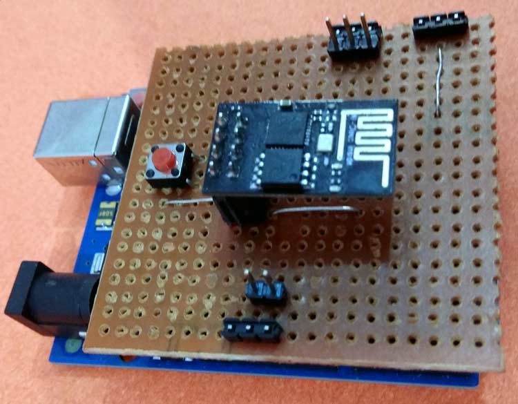
Here we have soldered all the components on a Perfboard so that it acts as Arduino shield.
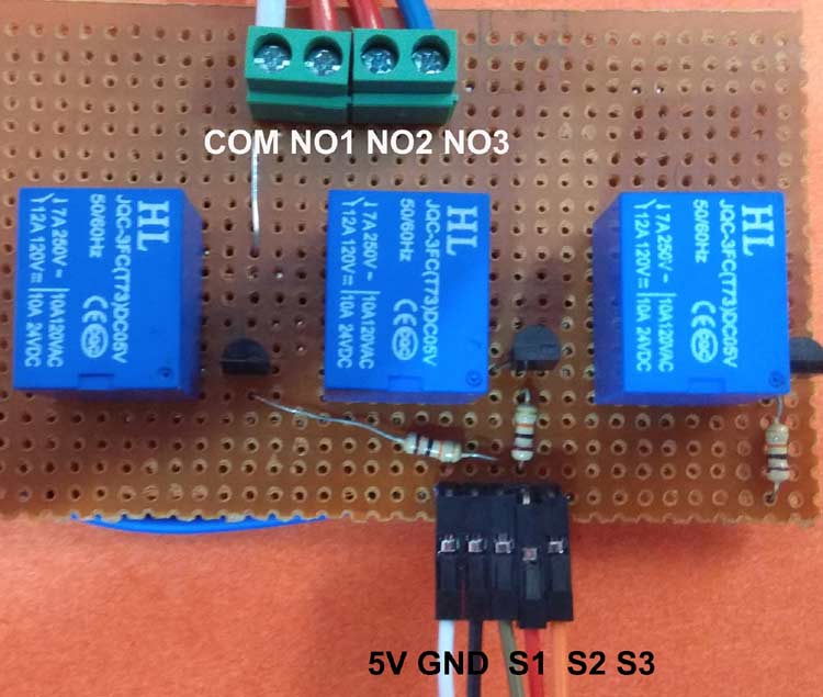
Similarly, we have also built a relay module on a Perfboard:
Setup Amazon Alexa App for Home Automation
After the successful completion of hardware setup and coding, now it’s time to set up the Alexa Android app. First, we need to search for any nearby smart devices through this app. To do so turn on your Alexa device and then open your Alexa app and click on option “Devices” and then click on the “+” sign which asks you to “Add device”. Then click on “Add device”, in the type of device click “other” and then select discover devices. Then your Alexa app should search for the device which may take up to 45 seconds.
Note: Alternatively we can also discover the devices using the voice command “Alexa, discover devices”
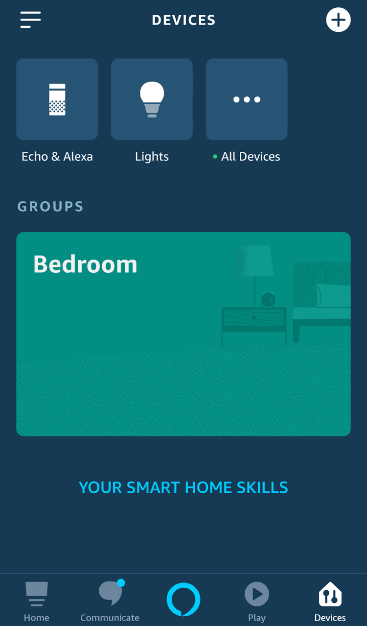
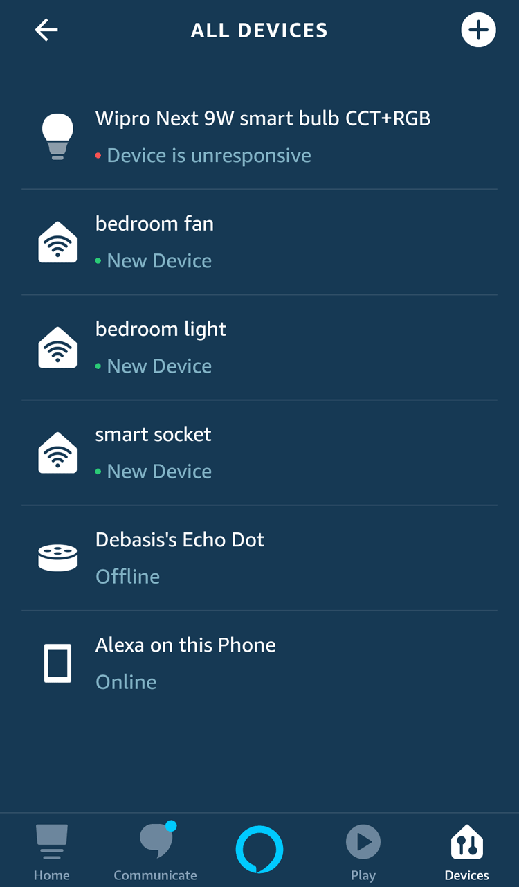
After completion of device discovery, you should be getting 3 new devices by name which we have given in the code. In my case, these are bedroom light, bedroom fan, and smart socket. Now the setup is ready for testing, just test by saying “Alexa, Turn on bedroom light” and it should return your feedback saying “Okay”, and the light should turn on. Similarly, we can test for all other commands.
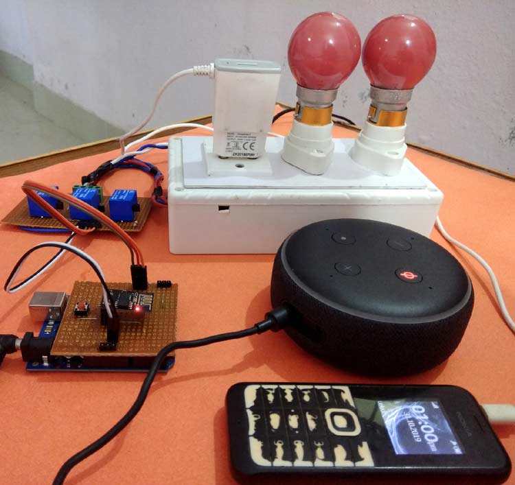
This is how the complete setup for Amazon Echo dot controlled Home appliances will look:
Complete code for ESP-01 with a demonstration video is given below.
Complete Project Code
#include <Arduino.h>
#include <ESP8266WiFi.h>
#include "fauxmoESP.h"
#define ssid "admin"
#define pass "12345678"
#define device1 "bedroom light"
#define device2 "bedroom fan"
#define device3 "smart socket"
fauxmoESP fauxmo;
void wifi()
{
  WiFi.mode(WIFI_STA);
  WiFi.begin(ssid,pass);
  while (WiFi.status() != WL_CONNECTED)
  {
    delay(100);
  }
}
void setup()
{
  Serial.begin(115200);
  wifi();
  fauxmo.createServer(true);
  fauxmo.setPort(80);
  fauxmo.enable(true);
  fauxmo.addDevice(device1);
  fauxmo.addDevice(device2);
  fauxmo.addDevice(device3);
  fauxmo.onSetState([](unsigned char device_id, const char * device_name, bool state, unsigned char value) {
  Serial.printf("[MAIN](%s) state: %s\n",device_name, state ? "ON" : "OFF");
    if (strcmp(device_name, device1) == 0)
    {
      if (state)
        Serial.print("1");
      else
        Serial.print("2");
    }
    if (strcmp(device_name, device2) == 0)
    {
      if (state)
        Serial.print("3");
      else
        Serial.print("4");
    }
    if (strcmp(device_name, device3) == 0)
    {
      if (state)
        Serial.print("5");
      else
        Serial.print("6");
    }
  });
}
void loop()
{
  fauxmo.handle();
}
Comments
Thanks Mr. Goddey for your kind appreciation. To answer your question, i would say, in case you want to control the switching operation using PIC microcontroller, then it can be done simillar to Arduino is used this case. But for Alexa connection you must need a wifi module like ESP8266 or Raspberry Pi whatever you prefer and there should be a serial communication between PIC and Wifi Module to transfer the data from Wifi module to PIC. Hope this answers your question. Thank you!!
can i use mobile phone in replcement of alexa ??
or what are other alternative of amazon eco dot please explain

Hello
I was going through this project and it's really fascinating.
Please can I do this project with pic micro controller?
And how can I go about it