
By Rajesh
Air pollution has become one of the most serious environmental and public health challenges in the modern world. Harmful gases such as carbon monoxide (CO) and nitrogen dioxide (NO₂), mainly produced by vehicles, industrial emissions, and fuel combustion, contaminate the air we breathe and pose significant risks to human health. Among all affected groups, children are the most vulnerable because their lungs and immune systems are still developing, and they breathe faster than adults, increasing their exposure to toxic pollutants. Exposure to polluted air in early life can lead to asthma, reduced lung growth, respiratory infections, cardiovascular complications, and impaired cognitive development. Continuous monitoring of environmental conditions is therefore essential to protect children’s health and ensure a safe living environment.
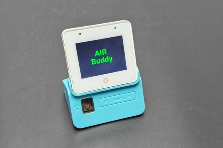
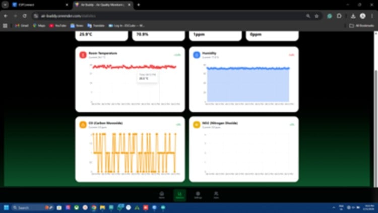
To address this issue, this project introduces AIR-Buddy, a real-time smart air quality monitoring device built using the ESP32-S3 Box. AIR-Buddy measures toxic gas concentrations along with temperature and humidity, displays the data locally on an integrated LCD screen, and provides remote monitoring with instant alerts through a smartphone-based AIR-Buddy web application. By offering real-time awareness and early warning notifications, AIR-Buddy helps families, schools, and communities take timely preventive actions and maintain a healthier environment for children

AIR-Buddy is a smart, real-time air quality monitoring device designed to detect harmful gases such as carbon monoxide (CO) and nitrogen dioxide (NO₂) along with temperature and humidity. It displays live environmental data on an in-built LCD screen and allows users to monitor air quality remotely through a custom smartphone web application. With configurable safety limits and instant push notifications, AIR-Buddy helps families, schools, and communities take timely action to protect health—especially for children who are more vulnerable to air pollution
Key Feature of AIR-Buddy
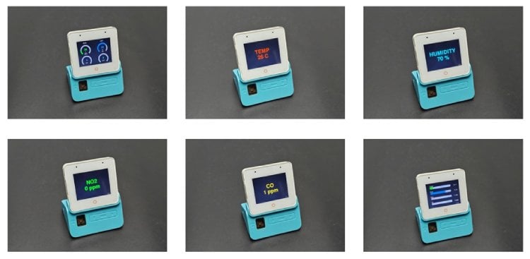
- Real-time air quality monitoring for CO, NO₂, temperature, and humidity
- Clear LCD display for instant local data viewing
- Wi-Fi connectivity for remote monitoring via smartphone web app
- Custom safety threshold settings for each environmental parameter
- Instant push notifications when pollution levels exceed safe limits
- User-friendly and portable design suitable for homes, schools, and workplaces
- An expandable system for adding more sensors, like PM2.5, in the future
Hardware used for building AIR-Buddy
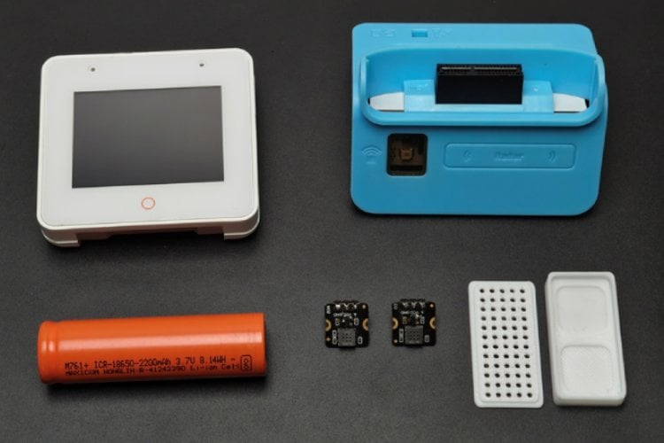
- ESP32-S3-BOX-3 -1 Nos
- MEMS CO GAS DETECTION SENSOR-1 Nos
- MEMS NO2 GAS DETECTION SENSOR-1 Nos
- Battery 18650 3.7V 2Ah 30A(15C) 1A-1 Nos
You can purchase all parts together from DigiKey
ESP32-S3-BOX-3
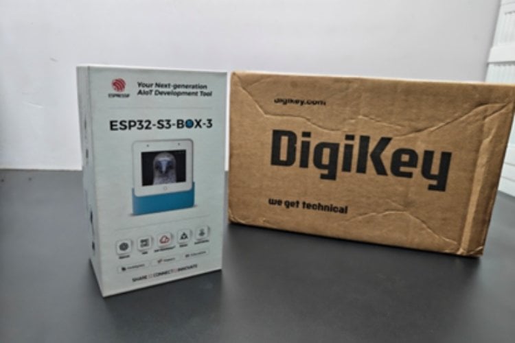
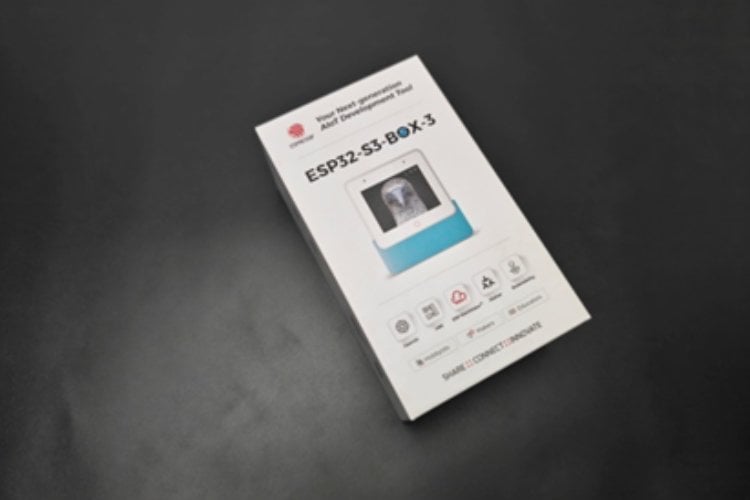
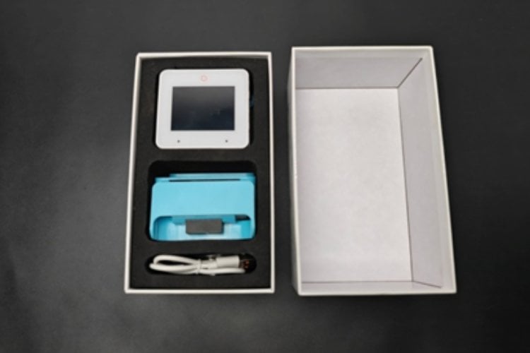
I bougtht the esp32 s3 box from digikey.com. The ESP32-S3-BOX-3 is an advanced AIoT development kit designed for smart embedded and Internet-of-Things applications. It is powered by the ESP32-S3 dual-core microcontroller from Espressif Systems and integrates wireless connectivity, multimedia features, and multiple sensors into a compact enclosure.This module includes a built-in LCD display, microphone, speaker support, Wi-Fi, and USB connectivity, making it highly suitable for real-time monitoring, human-machine interfaces, and smart environmental devices such as the AIR-Buddy air quality monitor. Its onboard processing capability allows continuous sensor data acquisition, local display visualisation, and wireless transmission to cloud or web applications.
MEMS CO GAS DETECTION SENSOR
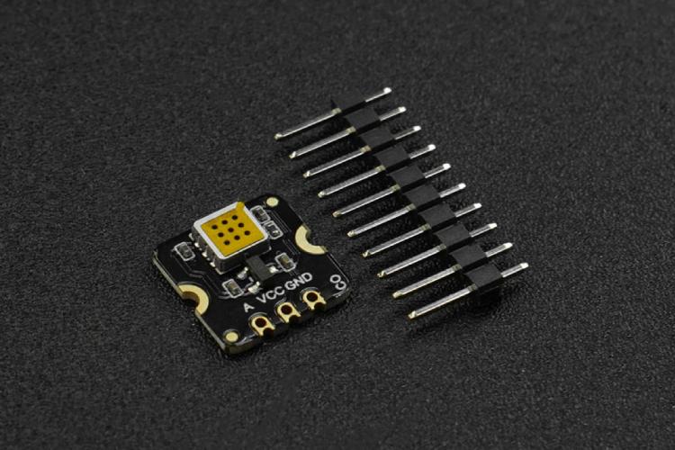
MEMS Carbon Monoxide CO Gas Detection Sensor employs state-of-the-art micro-electromechanical system (MEMS) technology, endowing the sensor with compact dimensions (13x13x2.5mm), low power consumption (<20 mA), minimal heat generation, a short preheating time, and swift response recovery. The sensor can measure carbon monoxide gas concentrations qualitatively and is suitable for carbon monoxide leak alarms and portable carbon monoxide detectors.
MEMS NO2 GAS DETECTION SENSOR
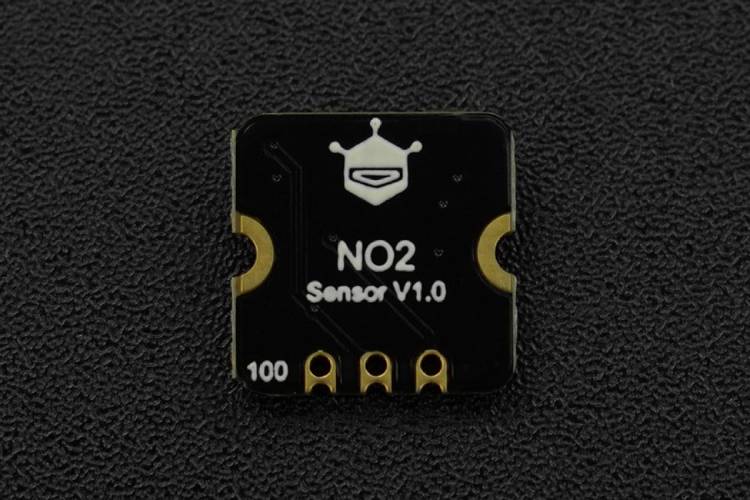
MEMS Nitrogen Dioxide NO2 Gas Detection Sensor employs state-of-the-art micro-electromechanical system (MEMS) technology, endowing the sensor with compact dimensions (13x13x2.5mm), low power consumption (<20mA), minimal heat generation, short preheating time, and swift response recovery. The sensor can qualitatively measure the concentration of nitrogen dioxide gas, and is suitable for nitrogen dioxide detectors, automobile exhaust detection, and other application scenarios.
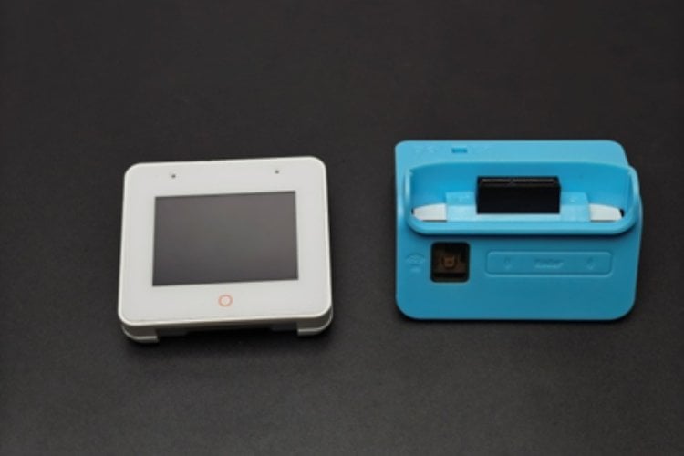
3.7 VOLT 18650 BATTERY
Since the ESP32 S3 box comes battery charger dock, we can use an 18650 battery to power the circuit.
Working of AIR-Buddy
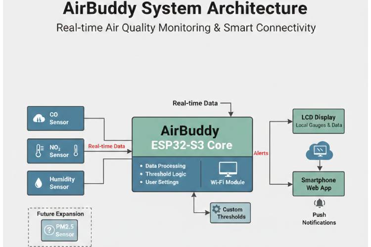
AIR-Buddy operates as an integrated real-time air quality monitoring system in which multiple environmental sensors, including carbon monoxide (CO), nitrogen dioxide (NO₂), and humidity sensors, continuously collect data from the surrounding atmosphere and transmit these real-time signals to the ESP32-S3 core for intelligent processing. Inside the controller, the incoming sensor values are filtered, converted into meaningful environmental units, and evaluated using embedded threshold logic along with user-defined safety settings, enabling the system to determine whether the measured air conditions remain within safe limits or require immediate attention. The processed information is simultaneously displayed on the built-in LCD interface to provide clear local visualisation of air quality parameters, while the integrated Wi-Fi module transmits the same real-time data to a dedicated smartphone web application for remote monitoring and historical observation. Whenever any pollutant concentration or environmental parameter exceeds the configured safe threshold, AIR-Buddy automatically generates alert signals that trigger instant push notifications on the user’s smartphone, ensuring timely awareness and preventive action to protect health, particularly for sensitive groups such as children. In addition, the architecture is designed with future scalability in mind, allowing the seamless inclusion of advanced sensors such as PM2.5 particulate matter detection, thereby making AIR-Buddy a flexible, expandable, and intelligent smart environmental safety companion for homes, schools, and workplaces.
CIRCUIT DIAGRAM

The AIR-Buddy hardware circuit is based on the ESP32-S3 Box microcontroller module, developed by Espressif Systems, which serves as the main processing and wireless communication unit of the system. Two external gas-sensing modules from DFRobot—the NO₂ sensor and the CO sensor are interfaced with the ESP32-S3 Box to enable continuous real-time detection of harmful air pollutants. Both sensors receive power through the shared VCC and GND connections provided by the ESP32-S3 Box, ensuring stable operation and a common electrical reference. The analog output of the NO₂ sensor is connected to GPIO 9, while the analog output of the CO sensor is connected to GPIO 10, allowing the internal analog-to-digital converter of the ESP32-S3 to sample gas concentration levels for further processing. In addition to these external gas sensors, the system utilizes the built-in AHT temperature and humidity sensor integrated within the ESP32-S3 Box to monitor ambient environmental conditions without requiring extra hardware connections. The microcontroller processes all acquired sensor data, evaluates user-defined safety thresholds, and prepares the information for real-time LCD display and wireless transmission to the smartphone web application. This integrated design ensures accurate multi-parameter environmental monitoring with minimal circuitry, forming the reliable sensing foundation of the AIR-Buddy smart air quality monitoring system.
Testing the Circuit on a Breadboard
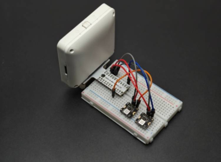
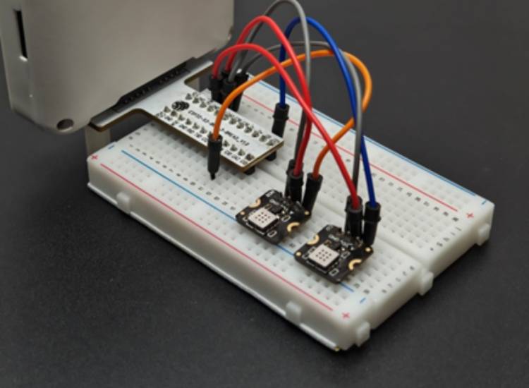
I assembled the circuit on a breadboard using an ESP32-S3-BOX development board along with two DFRobot gas sensor modules—one for detecting nitrogen dioxide (NO₂) and the other for detecting carbon monoxide (CO). Both sensors share the same power connections, with their VCC pins connected to the board’s supply voltage and their GND pins tied to the common ground. The analog output of the NO₂ sensor is connected to GPIO 9 of the ESP32-S3-BOX, while the analog output of the CO sensor is connected to GPIO 10. I tested the circuit and code using this setup
3D Design and Printing of sensor case
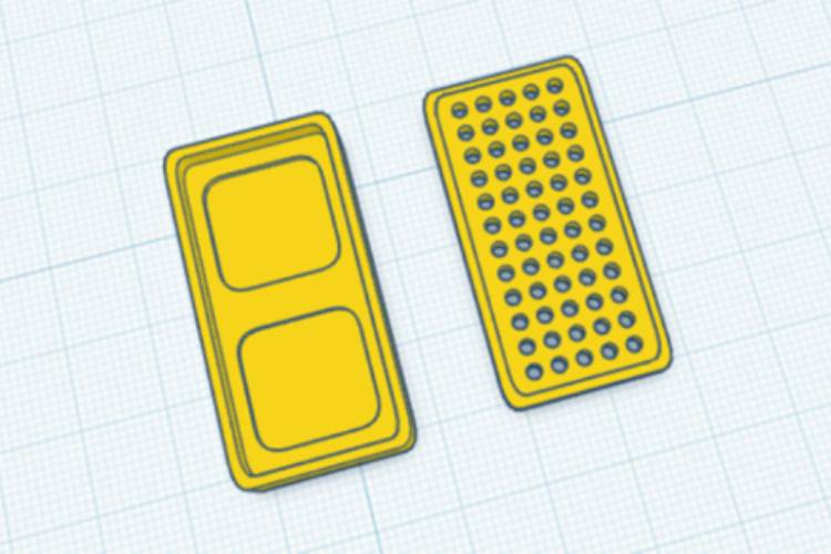
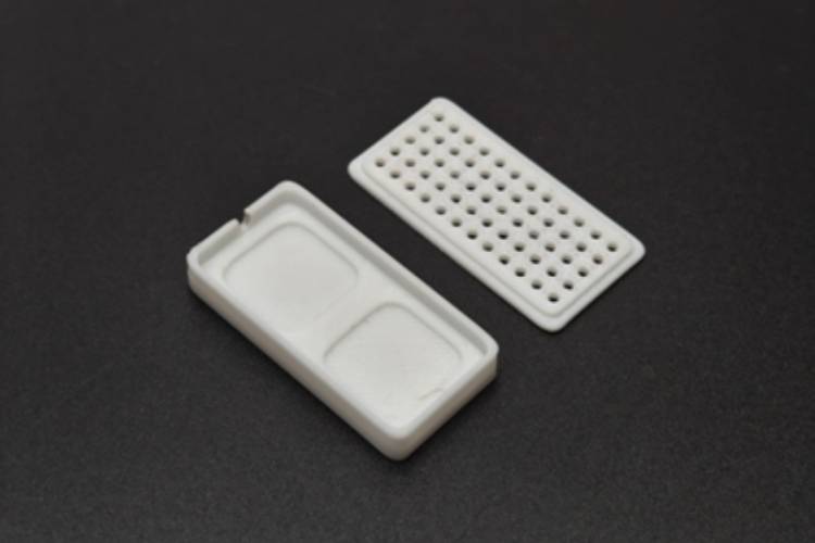
To securely house the sensing modules, I designed a custom 3D enclosure using Tinkercad, carefully sizing the structure to fit both gas sensor boards and provide proper openings for airflow, wiring, and mounting. The enclosure was then fabricated using a Bambu Lab A1 3D printer, ensuring good print quality, strength, and dimensional accuracy. This protective case not only keeps the sensors neatly organised and mechanically stable on the breadboard setup, but also shields the electronics from dust, accidental contact, and environmental disturbances while still allowing sufficient exposure for accurate gas detection.
Download the 3D file from here
Assembly of Airbuddy
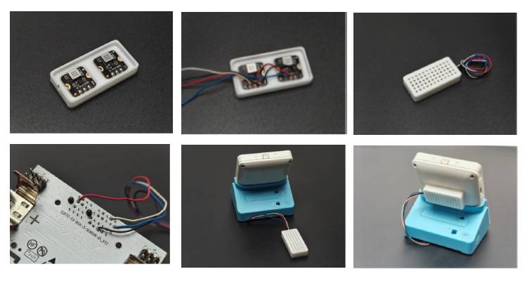
After printing the custom enclosure, I carefully mounted the gas sensors onto the designed slots in the case and connected them securely to the sensor base to ensure stable electrical contact and proper alignment. Once the wiring and positioning were confirmed, I fixed the assembled sensor units to the backside of the enclosure, making sure they were firmly held in place while still allowing adequate airflow for accurate gas measurement. This final mounting step completed the mechanical assembly, resulting in a clean, compact, and well-protected sensor module that is ready
Programming the AIR-Buddy using Arduino IDE
I programmed the ESP32-S3 using the Arduino IDE because it provides a simple, familiar, and beginner-friendly development environment. Since I am already comfortable working with Arduino-based tools and libraries, using the Arduino IDE made the coding, uploading, and debugging process much easier and faster. The straightforward interface, wide library support, and strong community resources allowed me to integrate the sensors, display, Wi-Fi configuration, and cloud communication smoothly without needing complex setup procedures. In this part I am explainig the code section by section, you can download complete code from the end.
#include <Arduino.h>
#include <Wire.h>
#include <WiFi.h>
#include <HTTPClient.h>
#include <ArduinoJson.h>
#include <ESPAsyncWebServer.h>
#include <LittleFS.h>
#include <DNSServer.h>
#include <AHTxx.h>
This part of the program imports all the essential software libraries required for the ESP32 to function as a complete internet-connected IoT device.
WiFi and HTTPClient provide the networking capability.
They allow the ESP32 to connect to a wireless network and communicate with an external web server by sending HTTP POST requests that contain sensor data.ArduinoJson is used to build structured JSON messages, which are the standard data format for modern web APIs.
Instead of sending plain text, the ESP32 packages temperature, humidity, and gas readings into an organized JSON object that the cloud server can easily understand.ESPAsyncWebServer together with DNSServer enables the ESP32 to create a captive portal configuration system.
When the device has no saved Wi-Fi credentials (or setup is forced), it becomes a temporary Wi-Fi hotspot and shows a web page where the user can enter network details and API keys.LittleFS is the internal flash file system of the ESP32.
It stores configuration data such as Wi-Fi name, password, server URL, and access token so that the device remembers these settings even after power is turned off.
#define LGFX_ESP32_S3_BOX_V3
#include <LGFX_AUTODETECT.hpp>
#include <LovyanGFX.hpp>
This part of the code activates the LovyanGFX graphics library with automatic hardware detection for the ESP32-S3 display board.
Auto-configuration means the library can internally select the correct display driver, pin mapping, and communication settings without requiring the programmer to manually configure them.
This significantly simplifies development and reduces the chance of hardware-specific errors.
LovyanGFX is selected instead of traditional graphics libraries because it provides several important technical advantages:
Higher rendering speed
The library is highly optimized for ESP32 hardware acceleration, allowing graphics, text, and shapes to be drawn much faster than with older graphics frameworks.
Faster rendering is essential for smooth user interfaces and real-time dashboards.Sprite (frame buffer) support
LovyanGFX allows drawing to an off-screen memory buffer called a sprite before sending the final image to the physical display.
This enables complex graphics composition without showing intermediate drawing steps on the screen.Flicker-free animation
Because the full frame is prepared in memory and then pushed to the display in a single operation, the user sees stable, tear-free visuals instead of partial redraw flickering.
This is especially important for gauges, graphs, and animated UI elements.
static LGFX lcd;
static LGFX_Sprite canvas(&lcd);
Two display layers are used in this system. The lcd represents the actual physical screen, while the canvas acts as an off-screen memory buffer where all graphics are drawn first. Instead of drawing directly to the screen, every visual element is rendered on the canvas and then transferred to the LCD in a single update. This approach prevents partial screen refreshes, resulting in a flicker-free display and a much smoother user interface
#define SCREEN_WIDTH  320
#define SCREEN_HEIGHT 240
uint8_t currentPage = 0;
const uint8_t TOTAL_PAGES = 6;
This section defines the essential parameters of the user interface, including the screen resolution, the current UI page index, and the total number of available pages. Together, these settings establish the structure for a multi-page touchscreen dashboard, allowing the system to manage screen layout, navigate between different interface pages, and maintain an organized visual flow for user interaction.
struct Config {
 char wifi_ssid[33];
 char wifi_password[65];
 char server_url[100];
 char access_token[70];
};
This structure is designed to store all persistent device configuration settings required for normal operation. It includes the Wi-Fi credentials, the cloud server address, and the API authentication token, ensuring the device can automatically reconnect to the network and securely communicate with the remote server. These settings are saved in LittleFS flash memory, allowing them to remain intact even after power loss or device restart, which provides reliable long-term operation without needing to reconfigure the system each time it boots.
void setup() {
 Serial.begin(115200);
 pinMode(TRIGGER_PIN, INPUT_PULLUP);
 lcd.init();
 lcd.setBrightness(255);
 canvas.createSprite(SCREEN_WIDTH, SCREEN_HEIGHT);
The setup() function defines the device’s boot sequence and prepares all essential subsystems for operation. It begins by starting serial communication at 115200 baud for debugging and monitoring. The trigger pin is then configured using INPUT_PULLUP, allowing the device to detect a pressed state that can force entry into configuration mode during startup. Next, the LCD hardware is initialized and its brightness is set to maximum to ensure clear visibility. Finally, a full-screen sprite buffer is created in RAM using the canvas, enabling all graphics to be drawn off-screen before being rendered to the display.Together, these steps prepare the system’s graphics engine, debugging interface, and configuration trigger, ensuring the device is fully ready for smooth UI operation and reliable setup handling immediately after power-on.
bool touchNow = isTouched();
if (touchNow && !lastTouch) {
 currentPage = (currentPage + 1) % TOTAL_PAGES;
 drawPage(currentPage);
}
This code implements edge-detection logic for touch input to control page navigation. The function first checks whether the screen is currently being touched and compares it with the previous touch state. A page change occurs only when a new touch press is detected (transition from not touched to touched), preventing repeated or rapid page switching while the finger remains on the screen. When a valid press is detected, the current page index is incremented and wrapped using the modulo operator with the total number of pages, enabling continuous circular navigation through all dashboard screens without exceeding the defined page range.
int ang = map(val,0,maxV,135,405);
int fillW = map(val,0,maxV,0,w);
This section converts raw sensor readings into visual positions for different gauge styles.
For the analog meter, the line int ang = map(val, 0, maxV, 135, 405); translates the sensor value into a needle angle spanning a 270° arc, which is standard in classic circular gauge design. This mapping ensures that the minimum reading starts at 135° and the maximum reaches 405°, creating smooth, proportional needle movement.
For the rectangular gauge, the line int fillW = map(val, 0, maxV, 0, w); converts the same sensor value into a horizontal bar width measured in pixels. This represents a straightforward linear interpolation, where higher values produce a longer filled bar, making the reading easy to interpret at a glance.
Web APP Development
Framework and Language
The backend of the AIR-Buddy web application is built using Node.js with TypeScript and the Express.js framework.
Node.js enables fast, event-driven server performance, while TypeScript adds strong typing, better code structure, and improved maintainability. Express.js provides a lightweight structure for creating APIs, routing requests, and handling server logic efficiently.
Database System
The system uses MongoDB as the database to store user accounts, sensor readings, and device information.
To manage database models safely and cleanly, Mongoose and Typegoose are used. These tools allow developers to define schemas, validate data, and ensure type safety when interacting with the database.
Authentication and Security
User authentication is handled using JWT (JSON Web Tokens) stored securely in cookies.
Passwords are protected through salting and hashing with bcrypt, preventing exposure even if the database is compromised.
Additional protections include CORS security to block unauthorized domains and environment variables to keep sensitive credentials hidden from the source code.
Real-Time Communication
To provide instant updates from the AIR-Buddy device, the backend integrates WebSocket communication using Socket.IO.
This allows live sensor readings and alerts to be pushed to connected users without refreshing the page, enabling real-time monitoring.
Notification System
The backend supports two alert methods:
- Web Push notifications using the web-push library for instant browser alerts
- Email notifications using Nodemailer with a Gmail account
These ensure users receive warnings when air quality becomes unsafe, even if they are not actively viewing the dashboard.
API Features
The backend exposes RESTful API endpoints that allow:
- Secure login and authentication
- Protected routes using middleware
- User account management
- Storage and retrieval of historical sensor data
- Real-time updates through WebSocket integration
This forms the core communication layer between the device, server, and frontend.
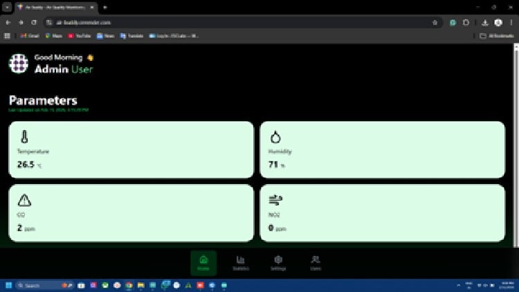
Frontend Development Explanation
Framework and Build System
The frontend is developed using React with TypeScript, providing reusable UI components and strong type safety.
The project uses Vite as the build tool, which enables very fast development startup and optimised production builds.
Styling and UI Design
Tailwind CSS is used for styling, allowing rapid creation of modern, responsive layouts.
Custom UI components include:
- Device information cards
- Navigation system
- Real-time data display panels
The interface also supports dark theme styling with gradient backgrounds for a clean, modern appearance.
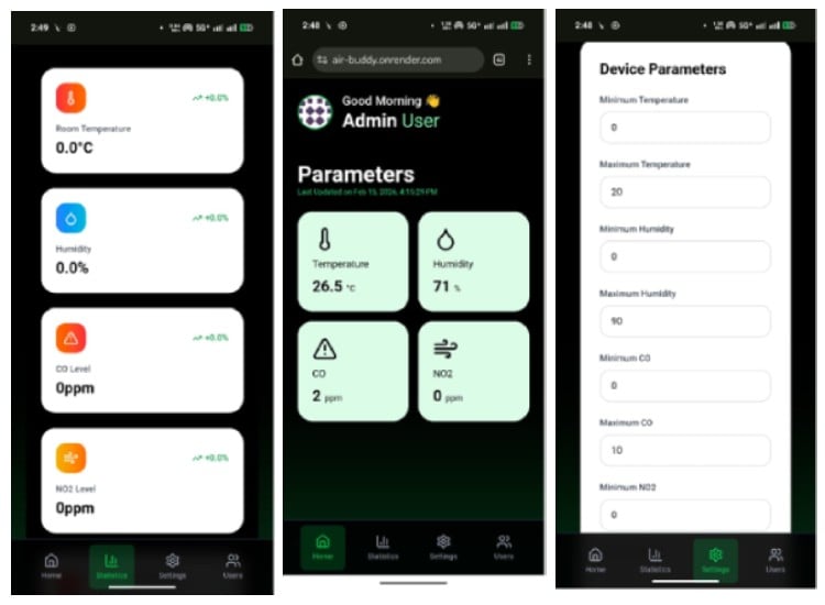
User-Facing Features
The frontend enables:
- Live visualisation of sensor data from AIR-Buddy
- Secure user login and authentication
- Fully responsive layout for mobile and desktop
- Smooth real-time updates without page reload
This ensures an intuitive monitoring experience for users.
Project Setup Explanation
Environment Variables
A .env file is created from .env.example to store configuration values such as:
- Server port
- MongoDB connection string
- Allowed frontend origin
- Gmail credentials
- Web Push VAPID keys
Keeping these outside the source code improves security and deployment flexibility.
Gmail App Password Setup
To send email alerts, a Gmail App Password must be generated from the Google account security settings.
This password is safer than using the main Gmail password and is stored in the .env file for Nodemailer authentication.
Web Push (VAPID) Setup
VAPID keys are required to send browser push notifications.
Public and private keys are generated and stored in environment variables, while the subject identifies the sender's email.
This enables secure and authenticated push messaging.
MongoDB Setup
The database can be configured in two ways:
- MongoDB Atlas (cloud) for remote hosting
- Docker local MongoDB for offline development
Both approaches provide persistent storage for users and sensor history.
Initial Setup and Data Seeding
After installing dependencies for backend and frontend, a seed script creates default users:
- Admin account
- Regular user account
This helps developers quickly test authentication and dashboard features.
Running the Application
During development:
- Backend runs on port 5001
- Frontend runs on port 3003
Both servers must run simultaneously for full system operation.
Production Build Process
For deployment:
- Frontend is built into optimised static files.
- Backend TypeScript is compiled to JavaScript.
- The production server has started to serve the full application.
This ensures high performance and stability in real-world use.
Docker Development Environment
Docker can automatically start a local MongoDB container with persistent storage and automatic restart.
This simplifies setup and ensures consistent development across different computers
Github Repository


