

Robotic arms are widely used in industrial automation, research, and educational projects. Building and controlling one is a great way to learn the fundamentals of embedded systems, motion control, and robotics.
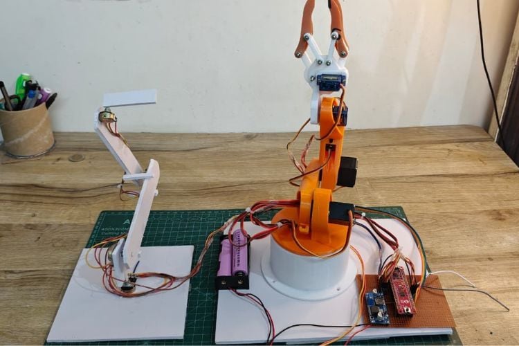
In this project, we will design and build a 4-degree-of-freedom (4-DOF) robotic arm controlled using potentiometers. Each joint of the arm is connected to a dedicated potentiometer, allowing its position to be adjusted directly for simple and responsive manual control.
The project is based on the PIC16F17576 Curiosity Nano development board. Along the way, you'll learn how a microcontroller can control devices in real time using basic input (ADC) and output (GPIO) functions instead of dedicated PWM hardware and integrate everything on a custom-designed PCB.
Whether you are getting started with embedded robotics or looking to understand the basics of real-time motion control, this robotic arm provides a practical platform for learning. It can also serve as a foundation for future additions such as a gripper, camera mount, or simple pick-and-place mechanism. In the process, you'll also gain hands-on experience with ADC-based sensing and real-time embedded control.
System Architecture and Components
The system consists of a microcontroller, input devices (potentiometers), and output actuators (servo motors). Each potentiometer provides an analog voltage that is read by the microcontroller and translated into a corresponding servo position.
Components
- PIC16F17576 Curiosity Nano
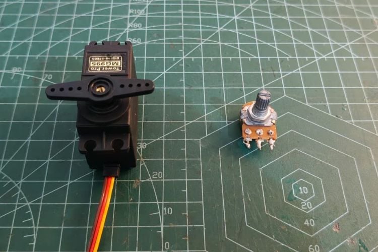
- Servo Motors (4x)
- Potentiometers (4x)
- External 5V Supply(lm2596) (alternative: LM2596S)
- Custom PCB
- 3D Printed Robotic Arm
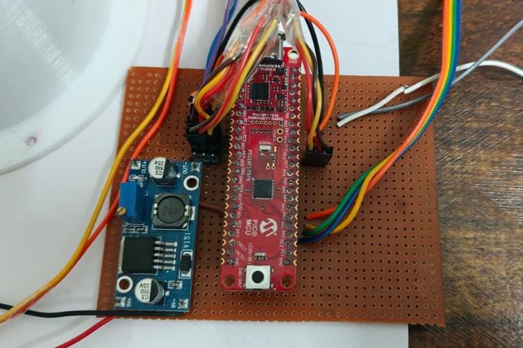
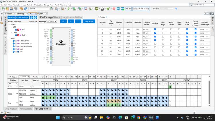
The PIC16F17576 Curiosity Nano is a compact and powerful development board based on Microchip’s 8-bit PIC microcontroller family, designed for rapid prototyping and embedded system development. It features an integrated programmer/debugger, multiple GPIO pins, a high-resolution ADC, and flexible peripheral modules, making it suitable for a wide range of applications. With support from MPLAB X IDE and MCC (MPLAB Code Configurator), it simplifies peripheral configuration and firmware development. Its precise timing capabilities and efficient architecture make it particularly well-suited for real-time control applications such as robotics and automation systems.
Pin Connections
| Function | Microcontroller Pin |
| Servo 1 | RC2 |
| Servo 2 | RC3 |
| Servo 3 | RC4 |
| Servo 4 | RC5 |
| Potentiometer 1 | RA0 |
| Potentiometer 2 | RA1 |
| Potentiometer 3 | RA2 |
| Potentiometer 4 | RA3 |
Circuit Diagram

Initial Servo Testing and Development Approach
Before implementing the full multi-servo system, individual servo testing was performed to validate signal generation and timing accuracy. This step ensured that the microcontroller could reliably generate the precise control pulses required for servo operation.
A simple sweep program was developed where the servo was driven by varying pulse widths in a continuous loop. This helped in understanding the relationship between pulse width and angular position, as well as verifying stable operation at a fixed 20 ms control frame.
During this phase, different pulse ranges and timing parameters were explored to achieve smooth motion and accurate positioning. This iterative testing process helped in fine-tuning the control logic before scaling the system to multiple servos.
Servo Sweep Code
#include <xc.h>
#define _XTAL_FREQ 32000000
#define SERVO_MIN 200
#define SERVO_MAX 2500
#define STEP 30
void delay_us_var(uint16_t us)
{  while(us--)
   {
       __delay_us(1);
   }
}
void main(void)
{
   ANSELCbits.ANSELC3 = 0;
   TRISCbits.TRISC3 = 0;
   uint16_t pulse = SERVO_MIN;
   int8_t direction = 1; // +1 forward, -1 backward
 while(1)
   {
       RC3 = 1;
       delay_us_var(pulse);
       RC3 = 0;
       delay_us_var(20000 - pulse);
        // Update pulse
       pulse += direction * STEP;
       // Reverse direction smoothly (NO pause)
       if(pulse >= SERVO_MAX)
       {
           pulse = SERVO_MAX;
           direction = -1;
       }
       else if(pulse <= SERVO_MIN)
       {    pulse = SERVO_MIN;
           direction = 1;
       }
   }
}
Code To Control 4 servos with ADC
#include <xc.h>
#include "mcc_generated_files/system/system.h"
#define _XTAL_FREQ 32000000
#define SERVO_MIN 600
#define SERVO_MAX 2300
void delay_us_var(uint16_t us)
{  while(us--) __delay_us(1);
}
uint16_t readADC(uint8_t channel)
{
   ADC_SelectChannel(channel);
   __delay_us(5);
   ADC_StartConversion();
   while(!ADC_IsConversionDone());
   return ADC_GetConversionResult();
}
void main(void)
{ SYSTEM_Initialize();
   uint16_t a0, a1, a2, a3;
   uint16_t p0, p1, p2, p3;
   uint32_t total;
   while (1)
   {
       // Read potentiometers
       a0 = readADC(channel_AN0);
       a1 = readADC(channel_AN1);
       a2 = readADC(channel_AN2);
       a3 = readADC(channel_AN3);
       // Map ADC values to servo pulse width
       p0 = SERVO_MIN + ((uint32_t)a0 * (SERVO_MAX - SERVO_MIN)) / 1023;
       p1 = SERVO_MIN + ((uint32_t)a1 * (SERVO_MAX - SERVO_MIN)) / 1023;
       p2 = SERVO_MIN + ((uint32_t)a2 * (SERVO_MAX - SERVO_MIN)) / 1023;
       p3 = SERVO_MIN + ((uint32_t)a3 * (SERVO_MAX - SERVO_MIN)) / 1023;
       // Generate servo signals
       RC2 = 1; delay_us_var(p0); RC2 = 0;
       RC3 = 1; delay_us_var(p1); RC3 = 0;
       RC4 = 1; delay_us_var(p2); RC4 = 0;
       RC5 = 1; delay_us_var(p3); RC5 = 0;
       // Maintain 20 ms control frame
       total = (uint32_t)p0 + p1 + p2 + p3;
       if(total < 20000)
           delay_us_var(20000 - total);
   }
}
Learning Experience and Platform Exploration
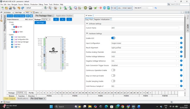
This project also marked my first hands-on experience with an industry-grade PIC microcontroller, specifically the PIC16F17576 on the Curiosity Nano board. Initially, adapting to the development environment and peripheral configuration required some exploration, especially when working with ADC and timing control. While experimenting with servo control, achieving the required low-frequency signal (~50 Hz) using standard PWM modules required careful consideration. The default PWM configurations were more suited for higher-frequency applications, so generating stable servo signals involved exploring alternative approaches. This led to the implementation of a software-based pulse generation method, which provided precise control over pulse width and timing. This approach not only solved the frequency requirement effectively but also offered greater flexibility for controlling multiple servos simultaneously. However, the platform proved to be highly capable and flexible. The integrated ADC, configurable I/O, and precise timing control made it well-suited for real-time embedded applications like robotic control systems. As the development progressed, it became easier to leverage these features effectively.
Curiosity Nano Robotic Arm GitHub Repository
Get the complete code and wiring diagram for this project from this GitHub repo link given below


Design Refinement and Optimization
While building the system, several practical challenges were encountered related to timing synchronization, multi-servo control, and signal stability. These were addressed through iterative improvements in code structure and timing logic.
Pulse timing was carefully adjusted to match servo requirements
Sequential signal generation was implemented for multiple servos
ADC reading and control timing were optimized for better responsiveness
This process not only improved system performance but also provided deeper insight into real-time embedded system design.
This project demonstrates a practical and efficient approach to real-time robotic control using a microcontroller. By combining ADC-based input processing with software-generated servo signals, it highlights how embedded systems can be designed even with hardware constraints.
The debugging process and iterative improvements played a crucial role in achieving a stable system, making this project a strong example of applied embedded engineering.
Complete Project Code
//Code To Control 4 servos with ADC :
#include <xc.h>
#include "mcc_generated_files/system/system.h"
#define _XTAL_FREQ 32000000
#define SERVO_MIN 600
#define SERVO_MAX 2300
void delay_us_var(uint16_t us)
{  while(us--) __delay_us(1);
}
uint16_t readADC(uint8_t channel)
{
   ADC_SelectChannel(channel);
   __delay_us(5);
   ADC_StartConversion();
   while(!ADC_IsConversionDone());
   return ADC_GetConversionResult();
}
void main(void)
{ SYSTEM_Initialize();
   uint16_t a0, a1, a2, a3;
   uint16_t p0, p1, p2, p3;
   uint32_t total;
   while (1)
   {
       // Read potentiometers
       a0 = readADC(channel_AN0);
       a1 = readADC(channel_AN1);
       a2 = readADC(channel_AN2);
       a3 = readADC(channel_AN3);
       // Map ADC values to servo pulse width
       p0 = SERVO_MIN + ((uint32_t)a0 * (SERVO_MAX - SERVO_MIN)) / 1023;
       p1 = SERVO_MIN + ((uint32_t)a1 * (SERVO_MAX - SERVO_MIN)) / 1023;
       p2 = SERVO_MIN + ((uint32_t)a2 * (SERVO_MAX - SERVO_MIN)) / 1023;
       p3 = SERVO_MIN + ((uint32_t)a3 * (SERVO_MAX - SERVO_MIN)) / 1023;
       // Generate servo signals
       RC2 = 1; delay_us_var(p0); RC2 = 0;
       RC3 = 1; delay_us_var(p1); RC3 = 0;
       RC4 = 1; delay_us_var(p2); RC4 = 0;
       RC5 = 1; delay_us_var(p3); RC5 = 0;
       // Maintain 20 ms control frame
       total = (uint32_t)p0 + p1 + p2 + p3;
       if(total < 20000)
           delay_us_var(20000 - total);
   }
}
