
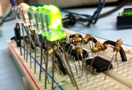
VU Meter or Volume Meter is very popular and fun project in Electronics. We can consider the Volume Meter as an Equalizer, which is present in the Music systems. In which we can see the dancing of LEDs according to the music, if music is loud then equalizer go to its peak and more LEDs will glow, and if music is low then lesser number of LEDs shall glow. Volume Meter (VU) is an indicator or representation of the intensity of sound level over LEDs and can also serve as a volume measurement device.
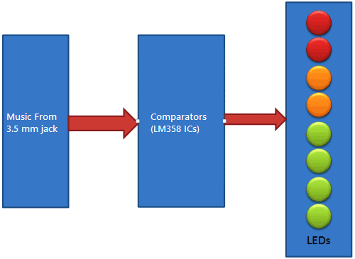
Previously we have built VU Meter using LM3914 in which audio input is taken from Condenser Mic and also built another VU Meter using Arduino in which audio input is taken from 3.5 mm jack. The later one was built on PCB as Arduino Shield. Today we are building another and most Simple Volume meter which only uses four LM358 op-amp ICs as major components.
Components Required:
- LM358 IC (4)
- 3.5 mm Audio Jack
- AUX cable
- 1k Resistors (16)
- 100k variable resistor
- 10k Resistor (2)
- Power Supply
- LEDs (8)
- Breadboard
- Connecting wires
- Music Source (Mobile or Laptop)
Working:
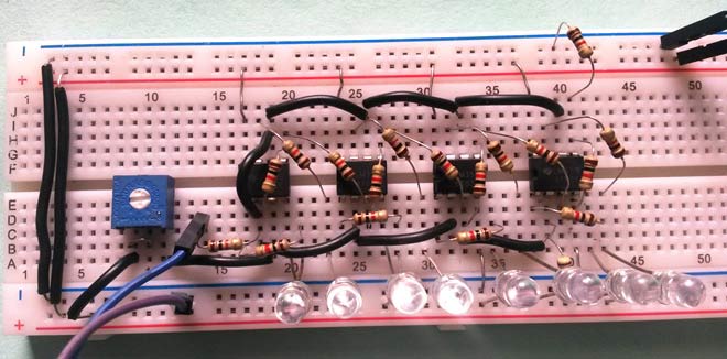
This VU meter is very simple, cheap and interesting project for the learner. In this project, we have used four LM358 dual op-amp IC which is easily available in the market and contains two comparator inside. User may also use two LM324 IC which has four op-amps inside, but it will complex the circuit on the Breadboard. Here we have used 8 comparators using four LM358 ICs, which will compare audio voltage signal with reference voltage. Reference voltage at not-inverting terminal (+), is adjusted by voltage divider circuit, built by using a pot and 1k resistors. 1k resistor is used at every comparator. Here one more advantage of POT (variable resistor) is that we need not to change values of all resistors for changing the reference voltage for each comparator, instead we can adjust it by only using the POT. In this circuit LEDs are connected at Reverse Logic, means negative terminals of LEDs are connected to the output of the comparators and when comparator output is high LED will be off and when output is Low then LED will be On. This circuit can work from 3.3v to 18v, but for a better result, I recommended to use 12v.
To start this cool LED equalizer, user needs to give power to the circuit and connect one end of 3.5mm Aux cable to the mobile or Laptop and the second end of the aux wire to the Circuit. Now increase the volume to max and calibrate the circuit by using a potentiometer. After calibration, user can use this circuit.
To demonstrate this project, I have sent the audio signal to two devices, one is our VU meter circuit and second is a woofer or audio amplifier. Woofer or amplifier is used to make the music listenable by us while operation, so that we can see the LEDs dancing according to the music signal. Check the demonstration Video at the end of this article.
Circuit Explanation:
In this VU Meter Circuit, we have used 8 LEDs, in which 2 LEDs are of Red color for Higher Audio Signal, 2 Yellow LEDs are for mediate audio signal and 4 Green LEDs are for Lower audio Signal. All LEDs are connected at the output of the 8 comparators present within four LM358 ICs. To drive LEDs in good brightness, user may reduce the value of resistors (1k) connected with LEDs. In the complete VU meter, we have used LM358 op-amps as a comparators and 1K resistor & 100k pot as a voltage divider for adjusting reference voltages at non-inverting terminal (+) of all the comparators.

Op-amp LM358:
Op-amps are also known as Voltage Comparators. When voltage at non-inverting input (+) is higher than the voltage at inverting input (-), then the output of comparator is High. And if the voltage of inverting input (-) is Higher than non-inverting end (+), then output is LOW. Know more about working of op-amp here.

LM358 is a Dual Low Noise Operational Amplifier which has two independent voltage comparators inside. This is a general purpose op amp which can be configured in many modes like comparator, summer, integrator, amplifier, differentiator, inverting mode, non- inverting mode, etc.
Comments
May I ask which program you used for making the circuit picture?
Sir i have only (3X LM358N IC) Can i follow your instruction?
thank, i appreciate alot.
how i can use Bluetooth with speak up click?
Hi
When a single IC can do the circuit job,it does not worth to use 4 ICs !!!!!!!!?????
I dont think you can do this with a single IC. The author has used 8 comparators for 8 different voltage levels and 8 LED's. He has also mentioned that he has chosen LM358 over LM324 to keep things simple.
So its not worth your comment, think before your comment something
Sir thank you for sharing this project to us. But could you please tell us more about the "woofer". I actually made one for the vu meter. But the music is not playing.

Thanks a lot! I appreciate it! But the music could've been better haha