

A tilt sensor is a sensor which opens and closes an electrical circuit when it is inclined beyond at certain angle. It can be used in tilt prevention devices, an alarm circuit and in many DIY projects. There are different types of Tilt sensor modules, for sensing the tilt the module can have a ball switch or mercury switch. In this circuit, we are using a Mercury-based tilt sensor.
Material Required
- Mercury Switch / Tilt Sensor
- BC547-NPN transistor
- Buzzer
- LED
- Resistor - 220 ohm
- Battery 9v
- Breadboard
- Connecting wires
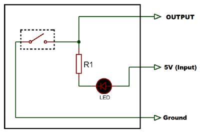
Circuit diagram

Tilt Sensor
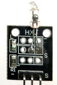
This is a Mercury switch based tilt sensor module that gives high at its output pin when tilted. It requires a 5V of DC input. It’s a three-terminal device consist of input, ground, and output. It has a glass tube consist of two electrode and liquid mercury ball. The liquid mercury ball closes and opens the circuit when inclined in a particular direction. The working and internal structure of the module is given below:
Internal Structure
Working of Tilt Sensor
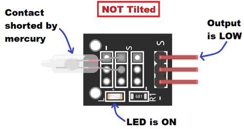
CASE 1: NOT TILTED
Initially, when it is in NOT tilted position as shown in the image below, it gives LOW output because of the liquid mercury complete the circuit by connecting the two electrodes. When the output is LOW on-board LED remain ON.
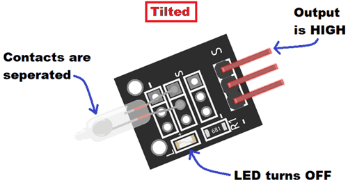
CASE 1: TILTED
When it is inclined in a particular direction or angle, the liquid mercury breaks the contact between the metal electrodes and the circuit gets open. Hence, we get HIGH output in this condition and the onboard LED turns off.
Working of Tilt Sensor Circuit:
Initially, the Tilt sensor switch is in closed state which means the output is LOW. Now as per the circuit, the output of the tilt sensor is feed to the base terminal of transistor BC547. Whenever the sensor inclined to an angle or tilted the output gets HIGH and triggers the NPN transistor into ON state. As the transistor turns ON, current through collector to emitter starts flowing and the LED and Buzzer, which are connected to the collector terminal, turns ON.
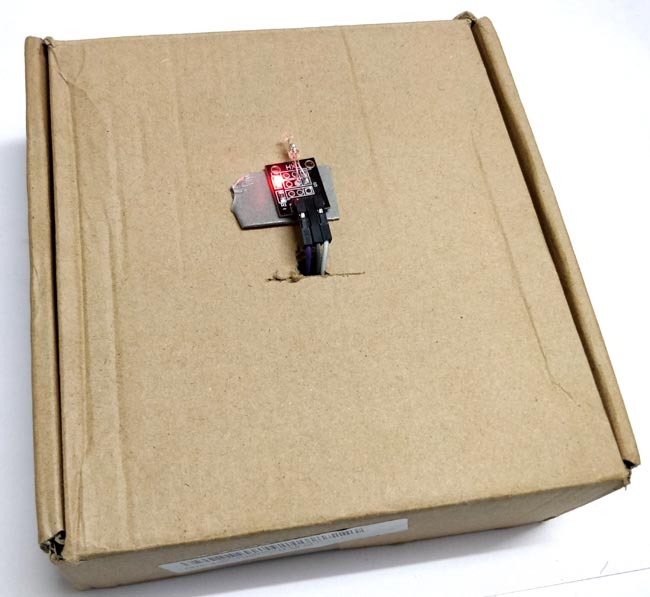
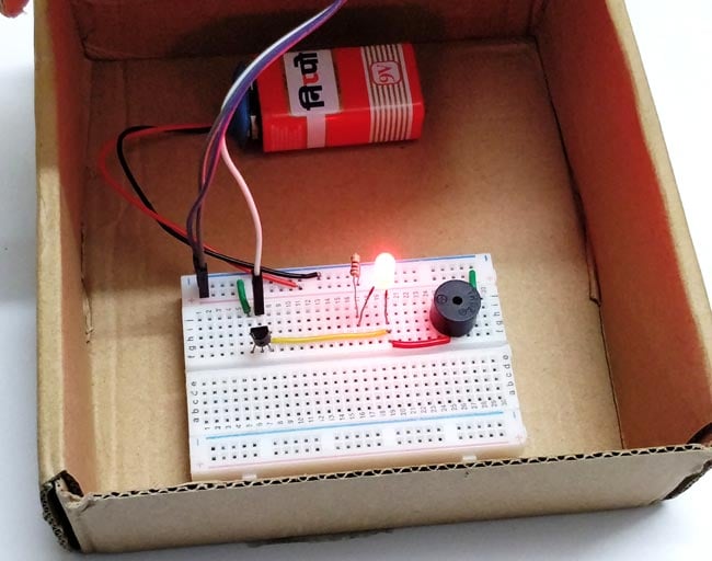
To demonstrate the tilt sensor working, we have arranged a box. The circuit is placed inside the box and the Tilt sensor is placed on the top of the box. So, whenever the box is opened, the sensor get tilted and LED & Buzzer turns ON. This can be cool hobby project like antitheft box, alarm box or secret document box.
