
You must have seen the Disco Lights or DJ lights, which Turn ON and OFF according to the beats of the music. These lights glow according to the length and pitch (volume) of music beats, basically these are designed to pick the high intensity sound like Bass sound. So these lights follow the high pitch beats in music like drum beats, and Turn ON and OFF according to music pattern. However the sensitivity of the circuit can be increased to pick the low notes too.
Previously we have built Dancing LEDs, which just follow a set pattern and we can only control the speed. Now we are taking this to next level, i.e. Music Operated Dancing LEDs, in which LEDs will flash according to music, just like Disco light, as discussed above. This Musical LEDs circuit is based on transistor BC547. This circuit is very simple and easy to build, it just requires few basic components and it looks very cool.
Components:
- Condenser Mic
- 5- NPN Transistor BC547
- Resistors- 10k (2), 1k (4), 1M (1)
- Ceramic Capacitor 100nF
- 4 – LEDs
- 9v Battery
- Breadboard and connecting wires
Working Explanation:
In this Simple LED Music Light Circuit, condenser mic picks up the sound signals and converts them into voltage levels. These voltage signals are further fed into R-C filter or HIGH PASS filter (R2 and C1), to eliminate the noise from the sound. Further a NPN transistor (Q1- BC547) is used to amplify the signals, from the High Pass filter. Then finally these music signals are given to the array of four transistors. Transistor in this array works as amplifier, and glows the four LEDs according to the sound pattern. This generates a very interesting sequence of dancing LEDs which follows the beats as per their intensity or pitch. We can also add more LEDs with transistor to make it cooler.

We can adjust the sensitivity of MIC by changing the value of R2 and C1, by using the formula for R-C filter:
F = 1/ (2πRC)
F is the cut off frequency, means filter only allow frequency above than F. It can be easily deduced that more the value of RC, less the cut off frequency and higher the sensitivity of MIC. And higher the sensitive of circuit means MIC can pick low volume sounds, hence LEDs can glow on low pitch music also. So by adjusting its sensitivity we can make it less sensitive to reacts only on high note beats or we can also make it more sensitive to react on every little beat in the music. Here we have set its sensitivity at moderate level.
Condenser Mic should be connected properly in the circuit, according to its polarity. To determine the polarity of MIC one should look at mic terminals, the terminal which have three soldering lines, is the negative terminal.
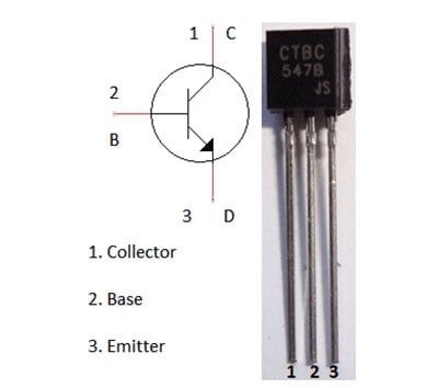
Transistor BC547 is a NPN transistor, which is used as a Amplifier here. NPN transistor acts as a open switch when there is no voltage applied on its Base (B) and it acts as closed switch when these is some voltage at its base. Generally 0.7 volt is enough to get it fully conducted.
Comments
Can you please provide me a circuit that uses sound as an input but works on NE555 timer.
As for my project i need to make a flash led circuit using above two technologies.
Are you talking about Simple Flashing LED using 555 Timer IC
Hey Maddy, i really love your project, its one amazing piece..... I've been trying to make little changes to mine but i've got no idea how to replace the mic with a speaker and audio jack :(... I hope you can show it on a circuit diagram... Thanks for understanding. :)
Check this one: Small Loudspeaker for Computer or Cell Phone
All the LEDs are starts glowing when battery is connected i put the circuit same as shown can any one help i didn't even connected the mic so that the mic is absorbing very little sounds
I learned that a condenser internally has a transducer... Please explain it and how transducer works also tell me about transistor.. In which mode it is here?
Can I know what can be the other components which can be used apart from Mic....
Can we use transistor S9014 ?
Hello,
Do you mind looking at my circuit and see what the problem is? I believe I have everything connected properly.
Thanks!
I have made all the connections as such in the circuit but its not working even after varying the value of r2 please help its urgent...
Hey,
What is the principle behind this experiment?
Can you please explain?
can I use any other capacitor at the place of ceremic capacitor 100nf
how to calculate the value of its components?
I want a sound indicating circuit .
by use 12v led
such an amazing job! this project is on the list of the projects we can do in linear circuit course at my uni. they also put this sites url as a reference
Can i use 5V battery instaed of 9v
What is different??
The calculation of the frequency gives a value of 1Hz, if I am not wrong. What does it mean, as in my view it should then allow all frequencies to go (too small value)
CAN WE USE BC 548 TRANISTOR
thanq sir ji bahut badiya circuit he
How this may work with a regular light bulb and AC? Thanks!
plz explain each component connection clearly, as we have tried three times it is not working.....
Hello
I am only testing with a single led
I used TIP 120 instead of bc547 and I am using a 12v power supply but the led is always ON !
my RC value are R=4.7Kohm and C=33uF I even used R=100Ohm but in vain ? so what's the problem
what is the conclusion?
what is yhe working frequency of circuit?
I want to use a 12V input for the circuit and 4 leds in series in every group. What changes do i have to make? Thank you!
Worked perfectly.
can we use as multiple leds with multiple resistors and transistors
I want to know that how these circuits are working? And what is the role of capacitor,will it effect on incresing or decreasing it.Can be add more LEDs and transistor in this cicuit without changing the configuration of the cicuit.
how it works?[what is the use of R3?]
Can I use BC548 instead of 547?Will my circuit work?
how to simulate it on multisim
we try to bilt this circuit .we hope we sucessed in this project
what are the applications of this project??
if i use 1w led which transistor is to be used instead bc547 and value of r4 please?
What changes should I do to replace mic with audio jack input??
Can i use a monophone pin instead of the mic
This is a nice work
can anyone please tell what is the function of capacitor in circuit?
Thanks a lot for this post, helped me a lot.
For those who can't get it to work ignore everything to the right of LED1 and replace your mic with a simple audiojack coming from your pc/radio/whatever. This way you can easier tune the volume (too high volume leads to leds being always on).
If you don't want to cut a cable the head of the jack should be ground.
I just have to thank you again.
Thanks to this post i just build a 6 "band/led" spectrogram.
Similar to your circuit but with 1 lowpass, 4 bandpass and 1 highpass filter in parallel each driving one LED amplified via an NPN transistor.
This is the first electronics "project" i did which is almost useable.
Thanks again,
an enthusiastic beginner
can I replace 3.5mm jack in the place of microphone
Can I use a plc (Programmable logic controller) in this circuit?
Would appreciate it if someone answered.
Hello,
Which specification is for LED. Are you using 12V LED or lower voltage LED
Can I use 5V supply.
Best regards
Mark
Q1 needs to be a BC557 PNP transistor.
what is the use of R1 over here?
Instead of using a condenser MIC, is it possible to directly use the headphone wires?
It means the headphone jack is plugged into the jack port in the smartphone, while the mic wire and ground wire are inserted in the board.
Then the music is opened on the smartphone

Hey Maddy.. Ur project is awsm..
I hve one question. This cct is on DC if I wan to connect ac current then?? Of 230v..