
Small Loudspeaker is a fun project to do, you can connect it to your Cellphone or Laptop through a 3.5mm audio jack and can enjoy your own loudspeaker. You can also connect it to any device which has a 3.5 mm audio output, like TV, music player, video games etc. We have used LM386 IC to amplify sound, with a few external components.
LM386 is a low voltage audio amplifier and frequently used in battery powered music devices like radios, guitars, toys etc. The gain range is 20 to 200, gain is internally set to 20 (without using external component) but can be increased to 200 by using resistor and capacitor between PIN 1 and 8, or just with a capacitor. Voltage gain simply means that Voltage out is 200 times the Voltage IN. LM386 has a wide supply voltage range 4-12v. Below is the Pin diagram of LM386:
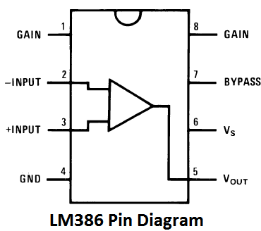
Pin description of LM386 along with the functions of external components used for amplification:
PIN 1 and 8: These are the gain control PINs, internally the gain is set to 20 but it can be increased up to 200 by using a capacitor between PIN 1 and 8. We have used 10uF capacitor C1 to get the highest gain i.e. 200. Gain can be adjusted to any value between 20 to 200 by using proper capacitor.
Pin 2 and 3: These are the input PINs for sound signals. Pin 2 is the negative input terminal, connected to the ground. Pin 3 is the positive input terminal, in which sound signal is fed to be amplified. We have connected one terminal of 3.5 audio jack to this input PIN 3 and the other terminal to Ground. 3.5 mm Pin is further connected to the Laptop’s audio jack.
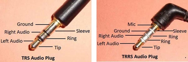
3.5 mm stereo audio jack is found in mostly headphones, there are generally two types 3.5 mm audio Jack, TRS (TIP RING SLEEVE) and TRRS (TIP RING RING SLEEVE). In TRRS one extra terminal is generally for Microphone. We have used TRS audio jack here and soldered two wire to it, one to Ground (Sleeve) and other to Right audio (Ring) . You can understand by below images:
Pin 4 and 6: These are the power supply Pins of IC, Pin 6 for is +Vcc and Pin 4 is Ground. The circuit can be powered with voltage between 5-12v.
Pin 5: This is the output PIN, from which we get the amplified sound signal.
The output signal has both AC and DC component, and DC component is undesirable and can’t be fed to Speaker. So to remove this DC component, a capacitor C2 of 220uF has been used.
Along with this capacitor, a filter circuit of Capacitor C3 (.05uF) and resistor R1 (10k) has been used at the output PIN 5. This filter also called the “Zobel network”, this electronic filter is used to remove the sudden High frequency oscillations or noise.
Pin 7: This is the bypass terminal. It can be left open or can be grounded using a capacitor for stability.
Components
- IC LM386
- 3.5 mm audio Jack
- Speaker 8ohm
- Capacitors- 220uF, 10uF (two), 0.05uF
- Resistor- 10k
- Battery 5-12v
Circuit Diagram and Explanation

I have cut the male to male 3.5 mm audio jack and solder two wires, but one should a female 3.5 mm audio jack for bread board. And connect one end of male to male audio jack to female audio jack and other end to computer.
This circuit is quite similar to my previous circuit “LM386 Based Audio Amplifier Circuit”, we just replaced the Condenser Mic with the 3.5 mm audio jack to provide the input sound. Also potentiometer has been removed, because there is already a sound control in computer’s Music player.
Comments
useful
Do you have the computations on how you arrive to those values of capacitors and the resistor?
Check the datasheet of LM386, these are the standard values to get the Gain of 200. We don't need to connect any external components to get the gain of 20.
where should the positive and negative terminal connect...
need info about Power Rating of capacitors mentioned ???
Any normal capacitor should work. 10uF caps are of 63v and 220uF is of 25v.
ic 810 audio and lm386 audio campers are the which is the best tell me please
Hello Jayant . I followed your steps, and everything seemed OK. My audio is from raspberry pi A+ 3.5mm jack, but the noise is very loud. Could you give me any suggestion to remove noise?
Try using High Pass filter at the Input, like we have used here: LED VU Meter using LM3914 and LM358
Sir, anyone tell how to play song from USB readed SD card connection with 3.5mm jack ..output two speaker...which ic I choose?.. Please describe
i like this project
If I remove the battery, will the project still function or not? Because I want to replace the battery with usb port
yes it will work
Can i make this using transistor bc548 instead of Ic?
You can try using 555 timer IC Simple Audio Amplifier using 555 Timer IC
It's very useful. I try to made it. connection was okk bt get the output very low. how it is increase??? plz give me suggetions..
hi. were doing this for project and i'm just wondering if you could tell me whats the power range of the three capacitors. because the shop is asking for volts..
They are of 63v (10uF) and 25v (220uF) ratings, but any volt rating capacitor should work here.
can IC LM 386 be used for making video output or any visual display circuit
I have make this project in ccb(copper circuit board) ..this circuit works well but the sound quality is not good..In this circuit nothing is used for voice cancellation...
Try using High Pass filter at the Input, like we have used here: LED VU Meter using LM3914 and LM358. Also Please read all the previous comments before asking questions, we might have answered them already.
Can LM358 be used to amplify a music input using the 3.5mm audio jack? Instead of using the LM368 IC chip?
Yes you can use LM358 but connections will be changed accordingly, check its datasheet. But LM386 is perfect for audio amplifier circuits.
as i am using high pass filter at the input . so i want to confirm that positive output terminal of high pass filter should be connected to pin3 of lm386 and the negative terminal should be grounded !! am i right ?? or any further connections are needed ?? plzz tell
Good day sir, can i use a 3 ohm 5W speaker ? Thank You :)
Frnds if anyone had done this project then plzz tell me is it working or not.

I want do this project