

Working with electricity can be a daunting and life-threatening task if you are a beginner in the electronic/electrical field, and things can go very wrong when electricity is not properly handled, which is why safety must come first in order to avoid injury, before starting work on an electric box and AC mains one need to verify that there is no AC leakage voltage. Which is why in this article we have decided to build a simple current detector circuit with 555 Timer and some passive components which can help you to detect open live lines with ease.
555 Timer IC Pinout
The Pinout of the 555 Timer IC is shown below the
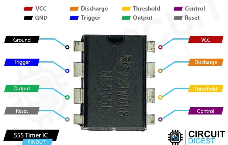
GND The Ground pin gets connected to supply ground.
Trigger Responsible for transition of the flip-flop from set to reset. The output of the timer depends 2 I on the amplitude of the external trigger pulse applied to this pin
Output This pin is normally connected to load as it is the only pin with output driven waveform
Reset Negative pulse applied to this pin to disable or reset the timer. When not used for reset 4 I purposes, it should be connected to VCC to avoid false triggering
Control Controls the threshold and trigger levels. It determines the pulse width of the output 5 Voltage IN waveform. An external voltage applied to this pin can also be used to modulate the output waveform
Threshold Compares the voltage applied to the terminal with a reference voltage of 2/3 Vcc. The 6 I amplitude of voltage applied to this terminal is responsible for the set state of the flip-flop
Discharge Open collector output which discharges a capacitor between intervals (in phase with output). 7 I It toggles the output from high to low when voltage reaches 2/3 of the supply voltage
VCC Supply Voltage (Typical = 5V, Maximum = 18V)
Learn more about 555 Timer IC by following the link.
Circuit Diagram

The 555 timer is the most commonly used IC for many different applications, which is what the working of the circuit is very simple when the voltage at pin-2 falls below ⅓ of the VCC the output pin of the 555 Timer goes high and the LED lights up and when its above ⅓ VCC the output goes low and the led shuts down. When the antenna detects an alternating input the output goes HIGH and LOW and the LED flashes accordingly.
Projects Using 555 Timer

Simple Time Delay Circuit using 555 Timer
If you are looking for a timer circuit without the intervention of a microcontroller, then this project is for you. Because in this project we have decided to design a simple on off delay with two buttons and 555 Timer IC that could set time delay with the help of a potentiometer.

Automatic Rain Sensing Wiper Circuit using 555 Timer IC
If you are looking for some cool projects and interesting ideas then this project is for you because in this project we have built a simple automatic rain wiper with 555 timer and handful of other components.

Ding Dong Sound Generator Door Bell Circuit using 555 Timer
If you are planning to build yourself a simple doorbell then this is the project you are looking for because in this project we have built a simple doorbell with 555 timer and some basic components.

Thank you!