
Door Bells are available in lot of variations in market which generate different sounds but the most common sound of a Door Bell is “Ding Dong”, so this time we have decided to make a Door Bell Circuit with a Ding Dong sound by using 555 timers.
Components Required:
- 555 Timer IC -2
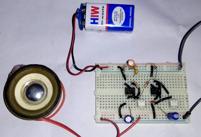
- Speaker
- Bread Board
- Resistors 330ohm, 2k, 10k ohm
- 50k variable resistor -2
- LED -1
- 100uF Capacitor -3
- Capacitor 100nf (104), 10nf (103)
- Jumper wire
- 9V battery or supply
- Push button
Circuit Diagram and Explanation:

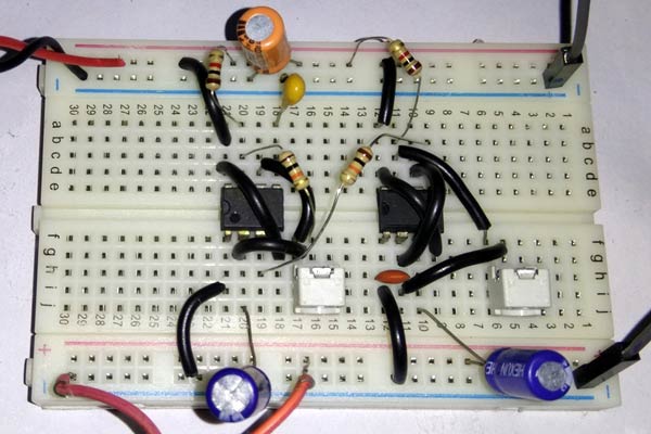
In this Ding Dong Sound Generator Door Bell Circuit, we have used two separate 555 Timer IC to generate ding dong signal. In first 555 Timer IC, we have connected a 1k (R1) resistor between Vcc & pin 7th of 555 Timer (U1). And a 10k (R4) resistor & 50k Pot (RV1) between pin 7 and 6. Pin 2 shorted with pin 6 and a 100uf C1 capacitor is connected to pin 2 or 6 with respect to ground. A 10nF (C2) capacitor is also connected to pin 5 of U1 with respect to ground. Pin 1 is connected to ground and pin 4 and 8 connected to Vcc. The output pin 3 of first 555 timer is connected to pin number 5 of second 555 Timer (U2) through 330 ohms (R4).
In Second 555 Timer IC, Pin 4 and 8 are connected to Vcc and 1 to GND. A 100nf (C3) capacitor is connected to pin 2 or 6 with respected to ground. A 1k (R3) resistor is also connected between Vcc and 7th of U2. And another 50K Pot (RV2) is connected between pin 7th and 6th. A speaker is connected to pin 3 of U2 through 100uF (C4) capacitor with respect to ground.
A 100uf (C5) capacitor is also connected between Vcc and ground. Finally, we have connected a 9v Battery to power the circuit.
Working Explanation:
In this Door Bell Circuit, we have configured 555 Timer IC in Astable Multivibrator mode. Here we have made two Astable multivibrators, for two 555 ICs, which are configured at different frequencies and frequencies can be adjusted by using attached potentiometers. The first 555 Timer multivibrator is generating around 1Hz frequency which is the time interval of ding and dong tone. The output of first Astable multi vibrator (U1) is applied to second Astable Multivibrator through pin 5 of second 555 timer IC (U2). The second multivibrator modulates it over its signal and generates different sound on the speaker connected at output Pin 3 of second 555 IC. RV1 is responsible for setting ding dong sound time interval and RV2 is responsible for the change is a sound signal.
Check the demonstration Video below for how to tune the circuit for getting proper Ding Dong sound with this 555 based door bell. Also check our previous Door Bell Circuit and all other 555 timer circuits.

What is the spefication of the speaker?