
Operational Amplifiers or op-amps for short are perhaps the most widely used component amongst all analog electronics. Because of their versatility, only a few external components are needed to configure them to perform a wide range of tasks like amplification, addition, subtraction, multiplication, integration and so on, hence the name operational amplifier, since it performs mathematical functions.
This functionality comes from the fact that they use feedback, which means sampling part of the output and adding or subtracting it from the input to achieve the desired result.
There are two types of feedback, positive feedback and negative feedback in op-amp, both of which will be covered in this article in detail.
Negative Feedback in Op-Amp
Negative feedback takes a part of the output and subtracts it from the input in such a way that the output is in equilibrium with the input. This means that any change in the input is followed by a similar change in the output.
The simplest example of negative feedback is the op-amp follower. In this case, the inverting input is connected to the output and the non-inverting input serves as the signal input.
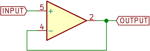
Following the rules of op-amp behaviour where the op-amp will try to maintain a 0V difference in voltage across the inverting and non-inverting inputs, we can understand that the output follows the input to maintain this 0V difference, hence the name follower.
If the input to this circuit was 1V, then the output would also be 1V, since the output is directly connected to the inverting input, hence making the voltage difference between the inverting and non-inverting pins 0V.
If you noticed carefully, you’ll realize that the gain of the circuit described is exactly 1, since the ratio of the input voltage and the output voltage is 1.
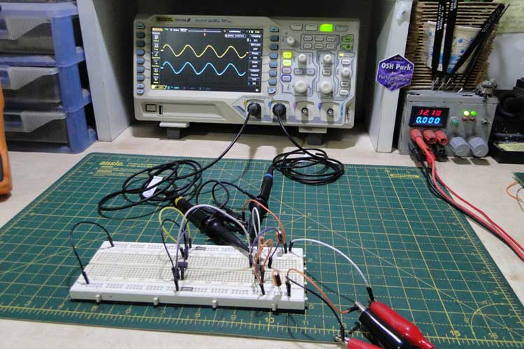
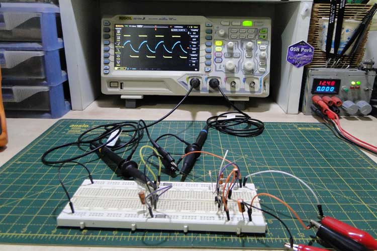
For the purposes of demonstration, this circuit was constructed using an LM741 op-amp, powered by a ±12V rail with a triangle wave input (from a triangle wave generator made in a previous article).
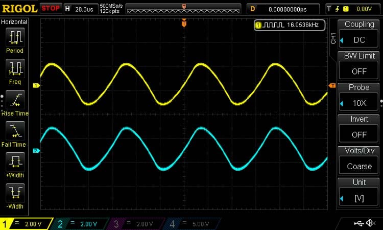
The above figure shows the waveforms of the circuit – the yellow waveform is the input, and the blue waveform is the output. The output is a replica of the input, so we know the follower works. Note the same vertical scale on both channels.
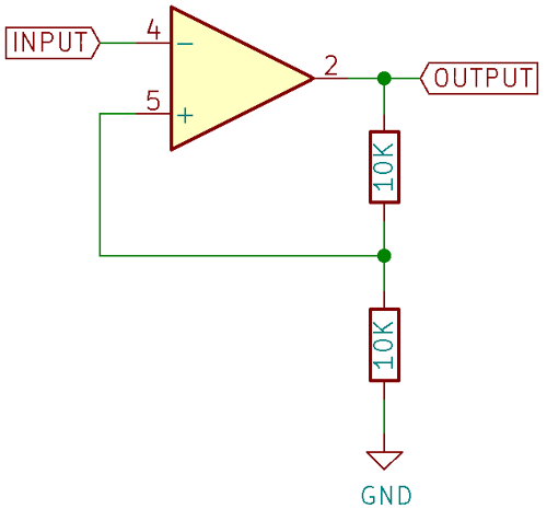
What if we want a gain other than 1? This can be done by adding a voltage divider to the output and connecting the inverting input to the middle of the divider. The non-inverting input serves as the signal input as usual.

In this case, both resistors are of equal value. If the input signal again is 1V, then the op-amp will try to change the output in such a way as to make the inverting input 1V in order to maintain a 0V differential across its input.
To do that, the output must go to 2V, so that the voltage divider output (and hence the inverting input) is at 1V.
This circuit has a gain of 2 – it multiplies the input voltage by a factor of 2.
It is clear that the output maintains equilibrium with the input – the output responds linearly to changes in the input, so this circuit is used as an amplifier, and this configuration is the classic non-inverting amplifier.
The previous follower circuit was modified by adding two resistors, and it is clearly seen that the output of the circuit is twice the input voltage.
The scope waveforms shown in the above figure illustrate how the output, which is the blue waveform, is twice the amplitude of the input, which is the yellow waveform.
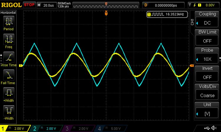
Note how the output is distorted due to the slew rate limitation of the op-amp. The gain of both the circuits described is much less than the open-loop gain of the op-amp itself, so it can be said that negative feedback reduces the overall gain of the system in exchange for stability.
Negative feedback op-amp applications:
Op-amp Negative feedback finds use mainly in amplifiers, where the input is multiplied by a factor called gain, and the output should be linear and stable with changes in input.
Positive Feedback in Op-Amp
The non-inverting amplifier circuit can be modified a little bit to create a circuit that has positive feedback.
The inverting and the non-inverting inputs of the op-amps are switched so that the inverting input becomes the signal input and the non-inverting input becomes the pin that receives feedback from the output through the voltage divider.
Now, when the voltage on the input becomes higher than the voltage at the non-inverting input, the output goes low. Since the op-amp is powered from a ±12V rail, the output sits at -12V and therefore the non-inverting input at -6V.
The output now stays latched at -12V till the input goes below -6V, at which point the output goes high to 12V, putting 6V at the non-inverting input.
Now the input has to cross 6V to make the output change state again.
Unlike the non-inverting amplifier configuration, this output of this circuit does not maintain equilibrium with the input, instead, it saturates to either supply rail in a non-linear fashion.
Positive feedback op-amp applications:
From this, we can conclude that positive feedback increases the gain of the system drastically, but is not stable and has only two states. Therefore, positive feedback cannot be used to create an amplifier since feedback is highly non-linear.
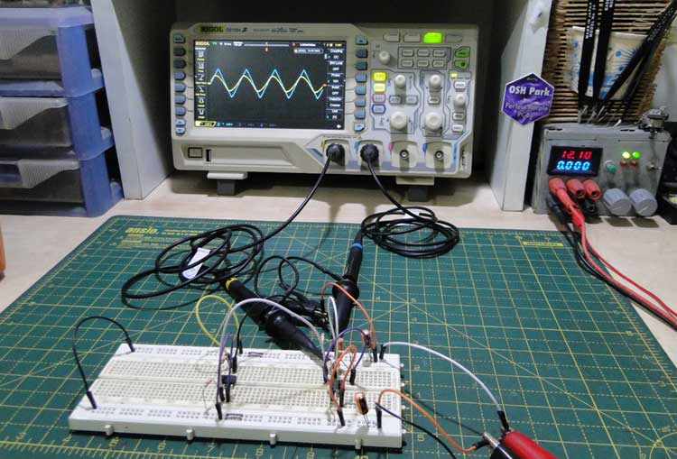
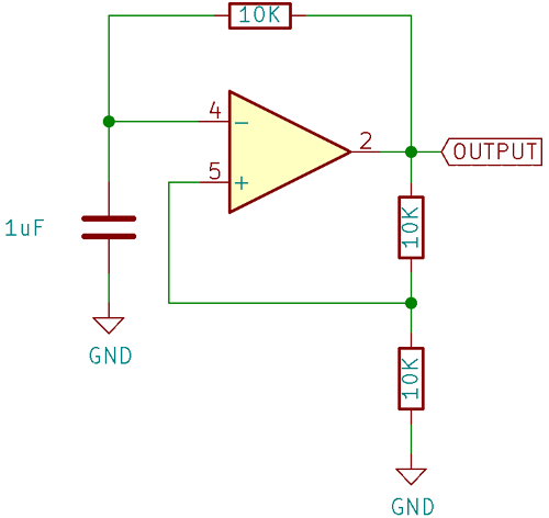
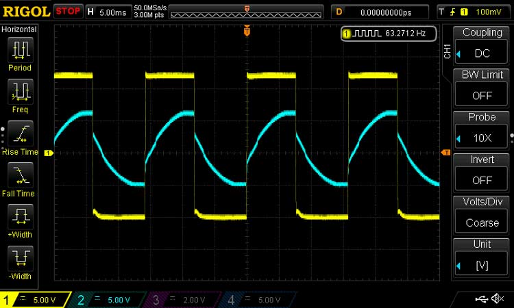
The best way to demonstrate an op-amp with positive feedback is a positive feedback oscillator. If we modified the previous circuit, adding a capacitor between inverting input and ground and a resistor between the inverting input and output, we can make a simple relaxation oscillator.
The scope waveform in the above figure shows the output of the oscillator on the yellow channel and the voltage at the non-inverting input on the blue channel. As you can see, the threshold voltage at the non-inverting input changes with every cycle of the oscillator, as described in the text above, between +6V and -6V.
We have tried to cover the positive and negative feedback in the article along with how they work, simple circuits to demonstrate them, and practical applications are also described.
