

Thyristors are semiconductor devices designed for high-power switching applications. Like Thyristors, transistors are also used as switching device. Transistors are the tiny electronic component that changed the world, we can find them in every device like TVs, mobiles, laptops, calculators, and earphones etc. Transistors are adaptable and versatile we can use them as amplifying and switching device but they cannot handle higher current. The main difference between the transistor and Thyristor is, Transistor need continuous switching supply to remain ON but in case of Thyristor we need to trigger it once only and it remains ON. For applications like alarm circuit which need to trigger once and stay ON forever, we cannot use the transistor. So, to overcome these problems we use Thyristor.
Thyristor operates only in switching mode. Thyristor can used for control high DC currents and loads. Thyristor behaves like Electronic Latch while using as a switch, because when triggered once it remain in conduction state until getting reset manually. In this project, we are going to show you how to control a load or DC motor using a Thyristor. You can replace the DC motor with any other DC load and control the any DC circuit.
Material Required
- 9v DC supply
- Thyristor – TYN612
- DC motor (as a DC load)
- Resistor (510, 1k ohm)
- Switch
- Push Button
- Connecting wires
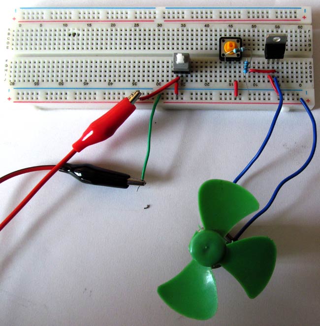
Circuit Diagram

The switch S1 in the circuit is used to reset the circuit or to turn OFF the Thyristor. The Push Button S2 is used to trigger the Thyristor by providing gate pulse through it. The position of switch S1 can be replaced by a normally-open switch across the Thyristor.
Thyristor - TYN612
Here, in the name of Thyristor TYN612, ‘6’ indicates the value of Repetitive peak off-state voltage, VDRM and VRRM is 600 V and ‘12’ indicates the value of On-state RMS current, IT (RMS) is 12 A. Thyristor TYN612 is fit for all modes of control like overvoltage crowbar protection, motor control circuit, inrush current limiting circuits, capacitive discharge ignition and voltage regulation circuits. The range of triggering gate current (IGT) is 5 mA to 15 mA. The operating temperature ranges from -40 to 125 °C.
Pinout Diagram of Thyristor TYN612
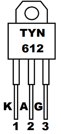
Pin Configuration of Thyristor TYN612
|
Pin NO. |
Pin Name |
Description |
|
1 |
K |
Cathode of Thyristor |
|
2 |
A |
Anode of Thyristor |
|
3 |
G |
Gate of Thyristor, used for triggering |
Working of Controlling DC Motor using Thyristor Circuit
Initially, the switch S1 and S2 remains in normally-closed and normally-open state respectively. When the supply ON, Thyristor remain reversed biased until the gate pulse provided. For providing gate pulse we have to use Push Button S2. As the S2 switch close, SCR turns ON and latches even we release the pushbutton S2.
When the Thyristor has self-latched into the ON state, the only way to stop the Thyristor from conducting is to interrupt the power supply. For that, we use switch S1, which cuts the power supply of the circuit and Thyristor get reset or turns OFF.
Resistance R1 used to provide sufficient gate current to turn ON the SCR. Resistance R2 is used for decreasing the gate sensitivity and increase the dv/dt capability. Therefore, it prevents Thyristor from false triggering. Learn more about Thyristor and its triggering methods here.

hi sir
how can I control the speed of motor for this circute by variable resistance ?