
There are a large number of injuries resulting from electrical shocks especially while maintaining and repairing electrical lines and towers. It is very difficult to isolate and check the presence of voltage in the wires without cutting it. A contactless voltage detector could come in very handy when dealing with such situations to be sure about no presence of voltage before performing any task related to reconditioning of electrical systems. Similarly, at home before rectifying a fault in an electronic device, it is always advised to be sure that there is no voltage supply. A DIY Contactless Low-cost AC voltage detector is there to the rescue! It uses minimal resources and performs really well when brought to use for such purposes. Be it for identifying a live wire or distinguishing between line and neutral wires, a low-cost AC voltage detector can be used. You can also check out the broken wire detector circuit using CD4069 which also works very much similar to our circuit here.
Components Required for our Live Wire Detector Project
Listed below are the components that the module requires and you can find them in the local hobby store.
- 3 NPN transistors (BC 547/2N2222)
- 220 ohm Resistor
- 9 V Battery
- Light-emitting diode(LED)
- Buzzer
- Copper wire
Circuit Diagram and Connections for the AC Voltage Detector

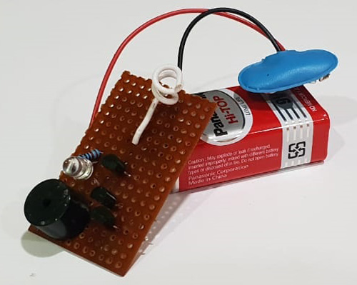
As the components are minimal, the making of live wire detector circuit is not very complex. It uses different components consisting of 3 NPN transistors, LED, 220 ohm resistor, 9V battery, and a copper wire. The antenna is connected to the base of the first NPN transistor(Q1) and the emitter of the first transistor (Q1) is connected to the base of the second transmitter (Q2) forming a Darlington pair (explained further). Again the emitter of the transistor (Q2) is connected to the base of the transistor(Q3) which then makes it acts as a switch and helps the LED glow. The collector regions of the transistors Q1 and Q2 are shorted and directly connected to the positive terminal of the 9V battery, whereas the collector of the transistor Q3 is connected to the LEDs (D1) cathode(negative) terminal and the anode(positive) terminal to one leg of the 220-ohm Resistor(R1), of which the other end is also connected to the positive terminal of the 9V battery.
Working of AC Voltage Detector
The copper wire is twisted in order to act as an antenna that detects any Electromagnetic induction around and generates a very low level signal. After which the series of transistors come into the play. The signal from the antenna probably in nano amperes enters the base of the transistor Q1 wherein Ic = β × Ib. Since the Beta(β) value is very large(around 110-800) this, in turn, gives us a larger collector to emitter current as the output . This process is repeated again with the emitter of the transistor Q1 going into the base of the transistor Q2. Hence, further increasing the current level Beta(β) times. The transistor Q3 acts as a switch and switches ON the LED and the buzzer when the current is supplied to the base terminal of the transistor Q3.
TIP: The sensitivity of the module can be altered by increasing or decreasing the size of the antenna coil.
Need for Multiple Transistors (Darlington Pair)
Darlington pairs are also known as super alpha circuits. It is an arrangement of standard Bi-junction transistors( NPN and PNP) whose base and emitter points are connected in order to increase the sensitivity and the gain of the transistor. For our live wire detector project, we can bring them into use in order to increase the gain and generate a greater current to switch the third transistor Q3. The output gain is simply the multiplication of the Beta(β) of the individual transistor and the input current provided to it. Hence, we receive the output with a higher gain.
Output current: β1 × β2 × Input Current
As two same NPN transistors are used to form the Darlington pair, then Beta1(β1)/hfe1 and Beta2(β2)/hfe2 are equal and the current gain will be:
β1 = β2
Ic = (β1 + (β1×β2) + β2) × Ib
Ic = (β^2) × Ib (since 2β is very small it is ignored)
Testing of AC Voltage Detector
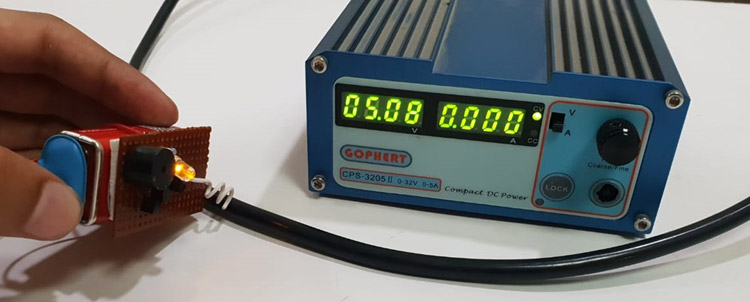
The DIY AC voltage detector module is powered by a 9V battery, which then is ready to detect any AC voltage. The module and the antenna are moved along the live wire and it can be seen that the LED glows and the buzzer starts to beep as shown in the image given below, where our circuit is placed near a live wire which is powering our RPS.
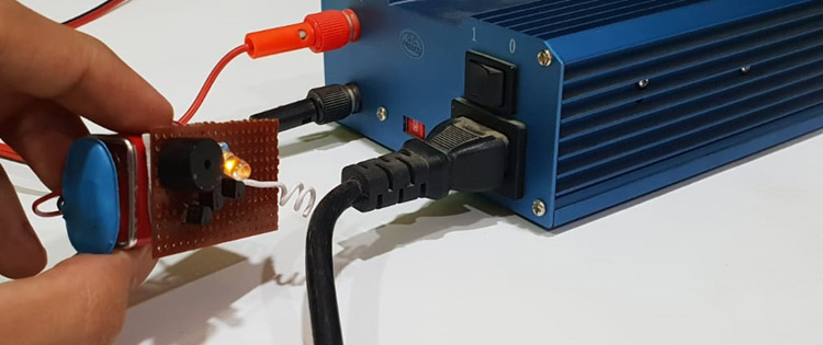
The electromagnetic signal is detected by the antenna on the circuit board and it, therefore, indicates that it is a live wire and should be handled with care. The complete working of this project can also be found in the video linked at the bottom of this page.
There are multiple ways to design an AC voltage regulator, but this by far is the cheapest amongst all. Although, there are some circuits that show a higher efficiency in detection and indication but the components used are a little expensive when compared to our design. Hope you have learnt something new and have enjoyed building your own AC voltage detector. If you have any questions, leave them in the comment section or use our forums.
