

Automobiles have been the primary mode of transportation for most of us and we depend on them for our day to day commute. Unfortunately there are lots of mishaps that could occur while driving an automobile and Brake Failures are one such case. Of course accidents cannot be avoided sometimes but they can sure be prevented by taking some preventive measures. In this project we will build a Circuit that can be attached to our Vehicles which will monitor the brake of our vehicle and provide us an audio-visual feedback if the brake fails.
Most economical vehicles depend on wire braking mechanism to apply brakes on the vehicle. This mechanism involves a Brake wire which runs from the brake lever to the braking mechanism set-up of the vehicle. It is this wire that gets pulled when we apply brakes to stop our vehicle. After a long use and tear these wires might get worn out and get cut at one point of time which eventually will cause a brake failure. So we will build a circuit that will monitor the continuity of this wire, the circuit will glow a green colour LED if everything is fine, but is the wire fails the circuit will blink a red colour LED also will beep a buzzer to alert the rider. Let us see how we can build this project...
Materials Required:
- Breadboard
- 555 Timer IC
- BC557 PNP Transistor
- Red and Green Colour LED
- 1uf and 0.1uf Capacitor
- 1K and 440K resistors
- Connecting wires
- Buzzer
Circuit Diagram and Explanation:
The circuit diagram for this brake failure indicator project is shown below

As you can see this brake failure indicator circuit is very simple and can be easily built on a breadboard. The main components in this project are the 555 Timer and the BC557 PNP transistor. The 555 Timer operates in Astable mode to produce clock pulse and the BC557 PNP Transistor monitors the Brake wire and decides which led should glow.
555 Timers in Astable Mode:
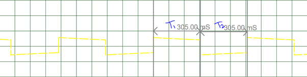
The Astable mode in a 555 timer is mainly used for Blinking LEDs or to do some periodic Turn On and Turn off actions. In this project we have configures the Timer to work with 0.3Sec on time and 0.3sec Off time. The value of the resistors R1, R2 and capacitor C1 decides the on and off time of the Pulse produced. The formulas for calculating the same is given below.
T1 = 0.693(R1+R2).C1 |
T2 = 0.693*R2*C1 |
T = T1+T2 |
F = 1/T |
Duty Cycle = T1/(T1+T2) |
In our case the value for R1 = 1000ohm and R2=440000ohm and C1=0.000001F. So using these formulae we can calculate our values to be

So the output of the pulse should remain turned on for 0.305Sec and turned off for 0.304 seconds which is almost the same when analyzed on the graph below which was obtained with help of a Digital Storage oscilloscope.
The BS557 PNP transistor controls the LEDs and buzzer. When the Brake wire is in proper condition the base of this transistor is provided with 5V through a current limiting (R4) Resistor. This also drives the Green LED light and disconnects the Buzzer and Red LED from ground thus keeping it turned off.
When the break wire is cut the base of the BC557 is also cut and thus the Green LED is turned off and the Buzzer and Red LED are connected to ground. Since the positive end of Buzzer and LED is connected to the 3rd pin of 555 timers which is wired in Astable mode operation, they blink/beep based on the duration set by the above calculation.
Working of This Brake Failure Circuit:
Once the connection is made power the circuit, make sure the Brake cable (here I have used a normal green wire to represent the brake cable) is connected across the +5V and base of BC557 through a resistor as shown in the circuit.
If everything works as expected you should see the Green LED turned on and the Buzzer and Red Light Turned Off. Now, cut/remove the brake cable the Red LED and the Buzzer should start flashing as shown in the video below.
Hope you understood the project and got it working
Comments
555 IC is an Analog IC. It is used in one out of its three operating mode like Monostable, Astable and Bistable.
Brake failure system
I want whole video of brake failure indicator using ic555 timmer with instruction
full video of brake failure cIRCUIT? CAN I SEE THAT HOW IT WORK OR ASSEMBLE? THANKS.
Sir,In the actual picture of circuit diagram the resistors used are of 5 in number..but in the circuit diagram there are only 3 resistors..does that make any difference??..
& also if we change the the capacitor C1 value to 0.1micro..what will happen??
The actual circuit diagram can be followed. I did not have the exact resistor values so I used two resistors in parallel to make up the value, thats why there appears to be more resistors in the picture. Otherwise, you can just follow the circuit Diagram.
If you change the value of C1 the buzzer beeping delay will be changed, other than that everything will be the same
full video of brake failure circuit ? CAN I SEE THAT HOW IT WORK OR ASSEMBLE?
can I pls get the full video of a brake failure indicator circuit with instuctions
I'm having trouble seeing how this works. I understand that when the brake wire is intact, Q1's base-emitter circuit is reverse biased and Q1 is off and the green LED is on. However, when the brake wire is cut and bias is removed from the green LED and it turns off, what supplies the bias to turn Q1 on and connect the buzzer/red LED to ground? There has to be some base current from someplace to turn Q1 on. No?
Hi Rick, the transistor used here is BC557 which is a PNP transistor. So you know what!
Kamrad, you should practice your electronic skills. Voltage regulator can be omitted, timer works well up to 15 V. Transistor here is used as one diode (b-c junction), b-e junction is always closed. Green diode will be always lit, with different brightness. Red diode should have a resistor too. Also nearly all metallic parts in cars are grounded, but in this circuit brake wire should be at positive voltage. This can not be done in real car. I suggest to turn this circuit upside-down and it will be nice. Your questions are welcome.
You are right vladimir, you suggestions can be implemented. I would surely edit it when I find time. But however people can also implement your solution as an upgrade once they understand how this circuit works.
Is there any specifications for buzzer in brake failure indicator circuit
Can i use 470k instead of 440k??
I just learned from one of your replies to the comments that you didn't had 440k ohm resistor as your ckt diagram value, so you paralleled two resistors to get that value.
I also can't find 440k ohm anywhere at my place, so it would be really kind of you if you could tell what values did you use to make 440k? Also do I strictly need to use that 440k value or it can be modified a bit?

Is the 555 ic have to be programmed?