

There are many ICs available to drive a 7 Segment display like IC 4026, 4033 etc and we have covered driving 7-segment using 4026 and using 4033. In this tutorial we are going to drive 7-segment display with IC 4511. This CD4511 IC is basically a BCD to 7-Segment decoder/driver IC, using which you can convert a binary number into a decimal number on the 7-segment display. For example, for printing number “2” on 7-segment display we will give 0010 to the inputs (A,B,C,D) of IC4511, like wise we can print 0-9 decimal number on single 7-segment display. We can be able to display a decimal number without using this chipset, but then we need 3 more pins and circuit will be complex, for saving pin we are using this IC.
IC 4511 has some inputs pins called BCD. We just have to make those BCD inputs High or Low according to the BCD code of that decimal number and we get the decimal number on display. For example: If you want to display ‘4’, the binary code of four is 0100 so we will give 0,1,0,0 to D, C, B, A inputs respectively and get the decimal number ‘4’ displayed on 7-segment.
Components Required
- CD4511 7-segment driver IC
- 7-segment display (common cathode)
- Push buttons
- Resistor (1k, 550 ohms)
- supply voltage 5v / 9v
- Connecting wires
- Breadboard
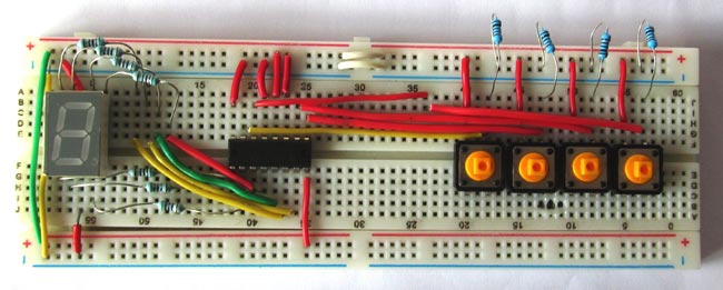
Circuit Diagram

In this BCD to 7-Segment Driver circuit, we are giving input through the push buttons as LOW or HIGH to the Pins 1, 2, 6, and 7. PIN 3 (lamp test) is directly connected to 5v, used for the testing of LEDs. Using this Pin, we can turn ON all the LEDs of the display to test the 7-segment display.
Pin 4 of 4511, which is blank input pin, used to turn off all the LEDs of the display, we are not using this pin in this circuit. We can turn off all the LEDs at a moment using this Pin. Pin 5 is connected to ground as we are using the pin to strobe the output. Pin 16 is connected to the power supply and Pin 8 is connected to the ground. Remaining Pins 9, 10, 11, 12, 13, 14, and 15 are connected with 7-segment display.
CD4511 7-Segment Driver IC
CD4511 is a BCD to 7-segment latch decoder driver IC formed with CMOS logic and NPN bipolar transistor output devices on an immovable structure. This IC is used where we need to driving common-cathode displays like 7-segment display, low voltage fluorescent display, and incandescent display. It has high output-current-sourcing up to 25mA comes with lamp test and blanking capability to test the display. It is having a DC supply input ranges from 3 to 18v with a normal operating temperature range from -40°C to +85°C.
Pin Diagram
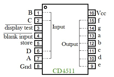
Pin Configuration
|
Pin no. |
Pin name |
Description |
|
1,2,6,7 |
B,C,D,A |
BCD input of the IC |
|
3 |
Display test/Lamp test |
To test the display |
|
4 |
Blank input |
To turn-off the brightness of the display |
|
5 |
Store |
Store or strobe a BCD code |
|
8 |
Gnd |
Ground |
|
9,10,11,12,13,14,15 |
e,d,c,b,a,g,f |
7-segment outputs |
|
16 |
Vcc |
Positive supply input |
7-Segment Display
A seven-segment display (SSD) is a widely used electronic display device for displaying decimal numbers from 0 to 9. They are most commonly used in electronic devices like digital clocks, timers and calculators to display numeric information. As its name indicates, it is made of seven different illuminating segments which are arranged in such a way that it can form the numbers from 0-9 by displaying different combinations of segments. It is also able to form some alphabets like A, B, C, H, F, E, etc. Learn more about 7-Segment Display here.
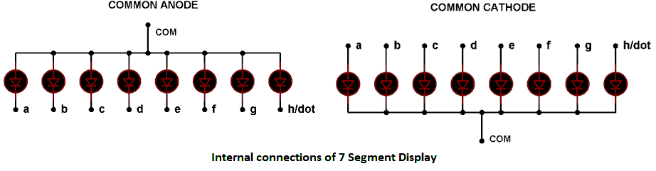
7 segment displays are among the simplest display units to display the numbers and characters. As shown in the above image of a 7-segment display, it consists of 8 LEDs, each LED used to illuminate one segment of unit and the 8thLED used to illuminate DOT in 7 segment display. We can refer each segment as a LINE, as we can see there are 7 lines in the unit, which are used to display a number/character. We can refer each segment "a,b,c,d,e,f,g" and for dot character we will use "h". There are 10 pins, in which 8 pins are used to refer a,b,c,d,e,f,g and h/dp, the two middle pins are common anode/cathode of all he LEDs. These common anode/cathode are internally shorted so we need to connect only one COM pin.
There are two types of 7 segment displays: Common Anode and Common Cathode:
Common Cathode: In this all the Negative terminals (cathode) of all the 8 LEDs are connected together (see diagram below), named as COM. And all the positive terminals are left alone.
Common Anode: In this all the positive terminals (Anodes) of all the 8 LEDs are connected together, named as COM. And all the negative thermals are left alone.
How to Display Numbers on 7 Segment Display using Binary Code?
If we want to display the number “0” on a common-cathode 7-segment display, then we need to glow all the LEDs except LED which belongs to line “g” (see 7 segment pin diagram above, so we need a bit pattern 00111111. Similarly to display “1”we need to glow LEDs associated with b and c, so the bit pattern for this would be 00000110. BCD code for both type of display common-cathode and common-anode given in the table below:
|
Digit to Display |
BCD code (A B C D)
|
Common anode ( h g f e d c b a)
|
Common cathode (h g f e d c b a) |
|
0 |
0000 |
11000000 |
00111111 |
|
1 |
0001 |
11111001 |
00000110 |
|
2 |
0010 |
10100100 |
01011011 |
|
3 |
0011 |
10110000 |
01001111 |
|
4 |
0100 |
10011001 |
01100110 |
|
5 |
0101 |
10010010 |
01101101 |
|
6 |
0110 |
10000010 |
01111101 |
|
7 |
0111 |
11111000 |
00000111 |
|
8 |
1000 |
10000000 |
01111111 |
|
9 |
1001 |
10011000 |
01100111 |
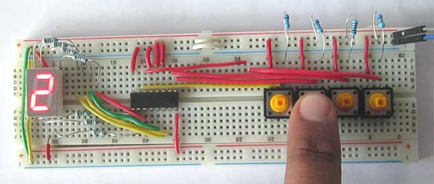
BCD to 7-Segment Decoder Circuit with IC 4511:
Initially the display will show Zero, as buttons are connected to pull down resistors and gives LOW as output when no button is pressed. So for getting any particular decimal number you just follow the table and you will get to know that out of 4 which buttons you have to press for displaying the particular number. Pressing any button will give a high input to the corresponding pin of 4511 and accordingly decimal number will be displayed on 7-segment. You can show decimal number from 0 to 9 on a single 7-segment display.
|
Displaying decimal number |
BCD code for IC4511 |
Push buttons |
|||
|
D |
C |
B |
A |
||
|
0 |
0000 |
Low |
Low |
Low |
Low |
|
1 |
0001 |
Low |
Low |
Low |
High |
|
2 |
0010 |
Low |
Low |
High |
Low |
|
3 |
0011 |
Low |
Low |
High |
High |
|
4 |
0100 |
Low |
High |
Low |
Low |
|
5 |
0101 |
Low |
High |
Low |
High |
|
6 |
0110 |
Low |
High |
High |
Low |
|
7 |
0111 |
Low |
High |
High |
High |
|
8 |
1000 |
High |
Low |
Low |
Low |
|
9 |
1001 |
High |
Low |
Low |
High |
Complete working of the circuit is shown in the Video Given below.

Pls if a digit is saved on the 4511 BCD decoder, will it remember the saved input after power OFF and is repowered?