

Power amplifier is the part of sound electronics. It is designed to maximize the magnitude of the power of given input signal. In sound electronics, the operational amplifier increases the voltage of the signal, but unable to provide the current, which is required to drive a load. In this tutorial, we will build a 40W Amplifier using TDA2040 Power Amplifier IC and two Power Transistors with a 4 Ohms impedance speaker connected to it.
Construction Topology for Amplifiers
In an amplifier chain system, the power amplifier is used at the last or final stage before the load. Generally, the Sound Amplifier system uses below topology shown in the block diagram
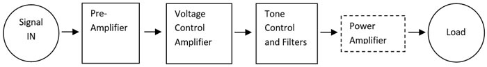
As you can see in the above block diagram, Power Amplifier is the last stage which is directly connected to the load. Generally, before Power Amplifier, the signal is corrected using Pre Amplifiers and Voltage controls amplifiers. Also, in some cases, where tone control is needed, the tone control circuitry is added before Power Amplifier.
Know Your Load
In case of Audio Amplifier system, the load and the load driving capacity of the amplifier is an important aspect in construction. The major load for a power Amplifier is the Loud Speaker. Power amplifier output depends on the load impedance, so connecting an improper load could compromise the efficiency of the Power amplifier as well as the stability.
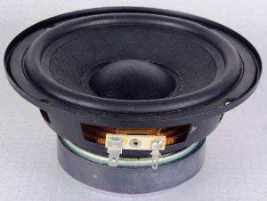
Loud Speaker is a huge load which acts as an Inductive and Resistive load. Power amplifier delivers AC output, due to this the impedance of the speaker is a critical factor for proper power transfer.
Impedance is the effective resistance of an electronic circuit or component for alternating current, which arises from the combined effects related to ohmic resistance and reactance.
In Audio electronics, different types of Loudspeakers are available in different wattage with different impedance. Speaker impedance can be best understood using the relation between water flow inside a Pipe. Just think loudspeaker as a water pipe, the water flowing through the pipe is the alternating audio signal. Now, if the pipe became bigger in diameter, the water will easily flow through the pipe, the volume of water will be bigger, and if we decrease the diameter, the less water will flow through the pipe, so the volume of water will be lower. The diameter is the effect created by the ohmic resistance and reactance. If the pipe gets bigger in diameter, the impedance will be low, so the speaker can get more wattage and the amplifier provide more power transfer scenario and if the impedance gets high then the Amplifier will provide less power to the speaker.
There are different choices as well as different segment of speakers are available in the market, generally with 4 ohms, 8 ohms, 16 ohms, and 32 ohms, out of which 4 and 8 ohms speakers are widely available in cheap rates. Also, we need to understand that, a amplifier with 5 Watt, 6 Watt or 10 Watt or even more is the RMS (Root Mean Square) wattage, delivered by the amplifier to a specific load in continuous operation.
So, we need to be careful about the speaker rating, amplifier rating, speaker efficiency, and impedance.
Construction of Simple 40W Amplifier
In our previous tutorials, we made 10Watt Amplifier using Op-amp and power transistors, also constructed a 25 Watt amplifier using TDA2040. But for this tutorial, we will build a 40W power amplifier which will drive an 4 Ohms impedance speaker. We will use the same TDA2040 which used in 25 Watt power amplifier, but to get 40 Watt power output we will use additional power transistors.
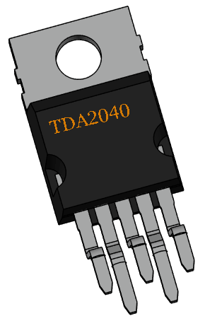
In the above image, TDA2040 is shown. It is available in most generic online shops as well as on eBay. The package is called ‘Pentawatt’ package with 5 output pin. The pinout diagram is pretty simple and available in the datasheet,
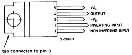
The Tab is connected to pin 3 or the –Vs (Negative supply source). Not to mention, the Heatsink connected with the tab also get the same connection.
If we check the datasheet, we can also see the features of this power amplifier IC
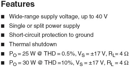
The features of the IC are quite good. It provides short circuit protection to ground. Also, thermal protection will deliver extra safety features due to an overload condition. As we can see the TDA2040 is capable to provide 25Watt output to a 4 Ohms load if a split power supply with +/- 17V output is connected. In such case, the THD (Total Harmonic Distortion) will be 0.5%. In the same configuration, if we get 30 Watt power output, the THD will become 10%.
Also, there is another graph in the datasheet which provides the relation between the Supply voltage and output wattage.
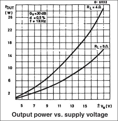
If we see the graph, we can achieve more than 26Watt output power if we use a split power supply with more than 15V output.
So, as we have already seen that it is possible to achieve 25 Watt continuous output through TDA2040. But we want to make 40 Watt power amplifier. So, this additional 15 watt, we need to add two power transistor NPN and PNP to provide additional amplification and output wattage across the 4 Ohms loudspeaker.
To, achieve this additional power amplification, we used matched pair transistor BD712 and BD711 power transistors. Both Transistors are available in TO-220C package.
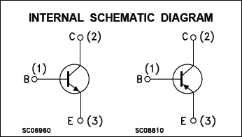
The pin out diagram of the BD711 and BD712 is
For perfect operation without THD compromised, we need a 36V power supply to achieve 40 Watt output. Although this circuit can be powered using 15V to 40VDC.
Required Components
To construct the circuit we need following components-
- Vero board (dotted or connected anyone can be used)
- Soldering Iron
- Solder wire
- Nipper and Wire stripper tool
- Wires
- Aluminum heat sink KS-58
- 36V Single power supply
- 4 Ohms 40 Watt speaker
- 4 pcs 1.5R Resistor 1/2 Watt resistors
- 4pcs 100k Resistor 1/4th Watt
- 12k resistor
- A 1R resistor with 2 Watt power rating
- 470nF capacitor
- 100uF capacitor
- TDA2040
- 1N4148 Diode two pcs
- 220nF capacitor
- 2200uF capacitor
- 4.7uF capacitor
- BD711 & BD712 Transistor pair.
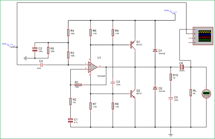
Circuit Diagram and Explanation

The schematic is 40 watt audio amplifier pretty simple; the TDA2040 is amplifying the signal and providing 25Watt RMS wattage. Additional power amplification is done using BD711 and BD712 transistor pairs. Input capacitor 470nF is the DC blocking capacitor which will only allow the AC signal to pass. One major thing is the Single supply voltage. As the amplifier is powered using a single supply, the input signal need to be lifted above a few volts so that the amplifier can amplify the signal in both a positive and negative peak. Resistors R6, R9 and R7, R8 are providing a bias voltage to the power transistors and power amplifiers. The R10 and C5 is the snubber or RC clamp circuit to protect the amplifier from a huge inductive load of the Loudspeaker.
Testing the 40watt Amplifier Circuit
We used proteus simulation tools to check the output of the circuit; we measured the output in the virtual oscilloscope. You can check the complete demonstration Video given below.
We are powering the circuit using 36VDC and the input sinusoidal signal is provided. The oscilloscope is connected across the output against 4 ohms load on channel A (Yellow) and the input signal connected across channel B (Blue).
We can see the output difference between the input signal and the amplified output in the video:-
Also, we checked the output wattage, Amplifier wattage is highly dependent on multiple things, as discussed before. It is highly dependent on the speaker impedance, speaker efficiency, Amplifier efficiency, construction topologies, total harmonic distortions etc. We could not consider or calculate all the possible factors which are created dependencies in amplifier wattage. Real life circuit is different than the simulation because many factors are needed to be considered while checking or testing the output.
Amplifier Wattage Calculation
We used a simple formula to calculate the wattage of the amplifier-
Amplifier Wattage = V2 / R
We connected an AC multi-meter across the output. AC voltage shown in the multi-meter is peak to peak AC voltage.
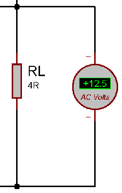
We provided very Low-frequency sinusoidal signal 200Hz. As in low frequency, the amplifier will deliver more current to the load and the multimeter will be able to detect the AC voltage properly.
The multimeter showed +12.5V AC. So, as per the formula, the output of the power amplifier at 4 Ohms load is
Amplifier Wattage = 12.52 / 4
Amplifier Wattage = 39.06 (40W approximately)
Things to Remember while Constructing 40w Amplifier
When constructing the circuit, The Power amplifier TDA2040 need to be connected with the heatsink properly. Larger heatsink provides a better result. Also, it is good to use audio grade rated box type capacitors for a better result.
It is always a good choice to use PCB for Audio related application. The best way to construct the PCB is by referencing IC manufacturer guidelines.
- Make the audio signal traces as short as possible to reduce unwanted noise coupling.
- The power transistors need to be connected with proper heat sinks. The KS-58 series heatsink can be used.
- Do not use a single large heatsink and fix TDA2040, BD711 and BD712. Use separate heatsinks for separate components otherwise, there will be short circuit conditions.
- Be careful about the speaker wattage otherwise, the speaker can be burned as well as damaged.
- Do not remove the clamp or snubber circuit, It is highly essential for the safety of power transistors and power amplifier.
- Do not apply large amplified signal in the amplifier, the THD will increase.
