
This project explains designing a home automation system which is controlled by a computer to switch On and switch Off various electrical and electronics devices. For demonstration we have used 3 zero watt bulbs which indicates LIGHT, FAN and TV. It uses Arduino Uno board as a controller and a 5V relay to connect light bulbs with the circuit.
There could be various types of communications to control devices like home appliances, industrial appliances, etc. Broadly we can categorize them as wired and wireless. For example in wireless communication we transmit signal using radio frequency (RF) and in wired communication we use wires. Wired communication can further be categorized as:
-
Parallel communication
-
Serial Communication
In parallel communication we use many wires depending on the data size in bits, i.e. if we need to transmit 8 bit then we would need a 8-bit wire. But in serial communication we only used two wires for transmitting data and receiving data as in serial communication data are transmitted serially i.e. bit by bit.
Components Required
-
Arduino UNO
-
Serial Cable
-
ULN2003
-
Relay 5 volt
-
Bulb with holder
-
Connecting wires
-
Bread board
-
16x2 LCD
-
Laptop
-
Power supply
-
PVT
Relay
We need a relay to connect the circuits with higher voltage AC appliances like bulb, TV, fan, etc. Relay is a kind of switch which is used for electronic to electrical interfacing. Relays contain a coil and some switching contact cores. There are different types of relays, like:
-
Single Pole Single Through (SPST).
-
Single Pole Double Through (SPDT).
-
Double Pole single Through (DPST).
-
Double Pole Double Through (DPDT).
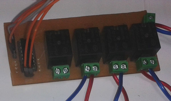
Here we have used single pole double through (SPDT) relay. SPDT relays contain five pins, in which 2 pin for coil and one is for pole and other two are namely "Normally Connected" (NC) and "Normally Open" (NO).
Circuit Diagram and Explanation

As shown in the above schematic diagram above, a 16x2 LCD module is used for displaying status of home appliances which is directly connected to arduino in 4-bit mode. Data pins of LCD namely RS, EN, D4, D5, D6, D7 are connected to arduino digital pin number 7, 6, 5, 4, 3, 2. For sending commands to arduino from laptop or PC we uses USB cable that we used for uploading program into arduino. And a relay driver IC ULN2003 is also used for driving relays. 5 volt SPDT 3 relays are used for controlling LIGHT, FAN and TV. And relays are connected to arduino pin number 3, 4 and 5 through relay driver IC ULN2003 for controlling LIGHT, FAN and TV respectively.
Here serial communication is used to control the home appliances. We send commands like LIGHT ON, LIGHT OFF, FAN ON, FAN OFF, TV ON AND TV OFF to control AC home appliances. After receiving the given commands, arduino send signal to relays which are responsible for switching on or off of the appliances.
When we press ENTER after typing one of any given command on hyper terminal or serial terminal, arduino performs relative task like turning on the “fan” and likewise other tasks. And a relevant message is also displayed on 16x2 LCD which is programmed in the code. (See the code section in bottom)
Code Explanation
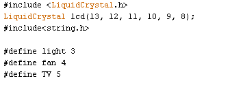
First of all we include library for liquid crystal display and then we defines data and control pins for LCD and home appliances.
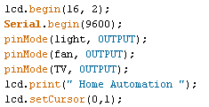
After it serial communication is initialized at 9600 bps and gives direction to use pin.
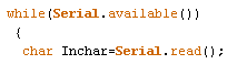
For receiving data serially we use two functions - one is Serial.available which checks any serial data is coming or not and other one is Serial,read which reads data that comes serially.
After receiving data serially we store it in a string and then wait for Enter.
When enter is pressed program start to compare received string with already defined string and if string matched then a relative operation is performed by using appropriate command that are given in code.
For using compare string we have used a library that is string.h which has some keywords like strcmp, strncmp, strcpy etc.
Complete Project Code
#include <LiquidCrystal.h>

#include<string.h>

LiquidCrystal lcd(13, 12, 11, 10, 9, 8);
#define light 3

#define fan 4

#define TV 5
char temp;

char str[10];

char i=0;
void setup()

{

  lcd.begin(16, 2);

  Serial.begin(9600);

  pinMode(light, OUTPUT);

  pinMode(fan, OUTPUT);

  pinMode(TV, OUTPUT);

  lcd.print(" Home Automation ");

  lcd.setCursor(0,1);

  lcd.print("    Using PC     ");

  delay(2000);

  lcd.clear();

  lcd.print("Keywords For ");

  lcd.setCursor(0,1);

  lcd.print("Controlling");

  delay(2000);

  lcd.clear();

  lcd.print("1. LIGHT ON");

  lcd.setCursor(0,1);

  lcd.print("2. LIGHT OFF");

  delay(2000);

  lcd.clear();

  lcd.print("3. FAN ON");

  lcd.setCursor(0,1);

  lcd.print("4. FAN OFF");

  delay(2000);

  lcd.clear();

  lcd.print("5. TV ON");

  lcd.setCursor(0,1);

  lcd.print("6. TV OFF");

  delay(2000);

  defualt();

  delay(1000);

}
void loop()

{

   if(temp==1)

   {

    if((strncmp(str,"FAN ON", 6))==0)

    {

     lcd.clear();

     digitalWrite(fan, HIGH);

     lcd.clear();

     lcd.print("Fan Turned On");

     delay(3000);

     defualt();

    }


    else if(strncmp(str, "FAN OFF", 7)==0)

    {

     digitalWrite(fan, LOW);

     lcd.clear();

     lcd.print("Fan Turned OFF");

     delay(3000);

     defualt();

    }


    else if(strncmp(str, "LIGHT ON", 8)==0)

    {

     digitalWrite(light, HIGH);

     lcd.clear();

     lcd.print("Light Turned ON");

     delay(3000);

     defualt();

    }


    else if(strncmp(str, "LIGHT OFF", 9)==0)

    {

     digitalWrite(light, LOW);

     lcd.clear();

     lcd.print("Light Turned OFF");

     delay(3000);

     defualt();

    }


     else if(strncmp(str, "TV ON", 5)==0)

    {

     digitalWrite(TV, HIGH);

     lcd.clear();

     lcd.print("TV Turned ON");

     delay(3000);

     defualt();

    }


    else if(strncmp(str, "TV OFF", 6)==0)

    {

     digitalWrite(TV, LOW);

     lcd.clear();

     lcd.print("TV Turned OFF");

     delay(3000);

     defualt();

    }


    else

    {

     lcd.clear();

     lcd.print(" Invalid Input");

     lcd.setCursor(0,1);

     lcd.print("   Try Again  ");

     delay(3000);

     defualt();

     }

   }

}

void serialEvent()

{

   while(Serial.available())

    {

     char Inchar=Serial.read();

     str[i]=Inchar;

     i++;

     lcd.print(Inchar);

     delay(50);

     if(Inchar == 0x0d)

     {

      temp=1;

      //Inchar=0;

     }

    }

}
void defualt()

{

  lcd.clear();

   lcd.print("Enter UR Choise:");

   lcd.setCursor(0,1);

   lcd.cursor();

   i=0;

   temp=0;

}
Comments
Please help me to understand
Please help me to understand these fragments of the code:
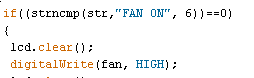
if((strncmp(str,"FAN ON", 6))==0) (how does strncmp work?)
{
lcd.clear();
digitalWrite(fan, HIGH);
lcd.clear();
lcd.print("Fan Turned On");
delay(3000);
defualt();
}
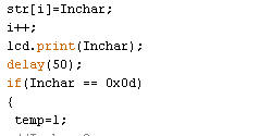
What is this function performing?
void serialEvent()
{
while(Serial.available())
{
char Inchar=Serial.read();
str[i]=Inchar;
i++;
lcd.print(Inchar);
delay(50);
if(Inchar == 0x0d)
{
temp=1;
//Inchar=0;
}
}
}
strncmp(str,"FAN ON", 6)
strncmp(str,"FAN ON", 6) compares the first 6 character of string in 'str' variable with the "FAN ON" string and return 0 if match occurs.
home automation rx and tx pin 0 and 1
hey
i wont to have any infos of the connetion when it work on gsm on pin 0 and 1 tx and rx arduino uno.
i have any infos that the sistem of home automation non work allown with comand sim card and when the impuls of rx and tx will be to great and break the arduno uno
i have infos to make a connection with conversation impuls tx and rx of 5v to 3.3v.
con you please help me
thanks
Fuse light problem
If light is fused then i need a back SMS... So which command is applied on to get this back sms.
Assalam o Alaikum ! Please
Assalam o Alaikum ! Please tell me that which commands are used for light on and off and so on. And also tell me that the working of strcmp function. I am little confuse in that function.
The code issues
wheh i am implemeting the above code i only see that lcd is on. rest there is no display on lcd screen nor any load is on or off. what should i do?
Sketch uses 3682 bytes (11%)
Sketch uses 3682 bytes (11%) of program storage space. Maximum is 32256 bytes.
Global variables use 496 bytes (24%) of dynamic memory, leaving 1552 bytes for local variables. Maximum is 2048 bytes.
how to solve this prb?

Assalam o Alaikum ! Please tell me that which commands are used for light on and off and so on. And also tell me that the working of strcmp function. I am little confuse in that function.