
You have seen Automatic Wiper System in luxury cars where Windshield Wiper automatically gets activated when there is Rain or if there is some water on the windshield. Electronic Wiper is very common device that is attached in every car to wipe the water on the windshield during the rain. But generally they are manually operated and we need to switch them ON manually. But today we are going to build Automatic Rain Sensing Car Wiper System using 555 Timer IC. This circuit automatically detects the rainfall and activates the wiper to clear the windscreen.
Components Required:
- 555 Timer IC
- L293D
- IC LM358
- Transistor BC557
- Resistors (1K, 10K, 2.2M)
- Capacitors (0.01uf, 0.47uf)
- DC Motor
- Rain Sensor
- Power supply (5-12v)
Circuit Diagram and Explanation:

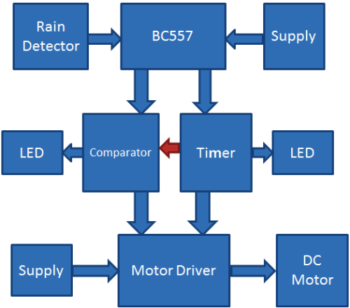
This Automatic Rain Sensing Wiper Control Circuit can be divided into four parts. First part includes 555 IC in Astable Mode, second part includes Comparator LM358, third part has Motor Driver circuitry using L293D and forth part is Rain Detector.
For Astable Multivibraror, we have used a 555 Timer IC for generating pulse in every 2-3 seconds (depends on capacitor value), means 555 Timer IC is configured in Astable mode. Output of Astable Multivibrator is directly connected to inverting pin of Comparator LM358 and Pin No 7 of Motor Driver L293D. Output of comparator is directly connected at pin 2 of motor driver IC. Comparator LM358 IC is used here for comparing 555 timer IC’s output voltage and reference voltage across comparator’s non inverting terminal, set by using Voltage Divider Circuit (R3 and R4). Two LEDs have been used, one at the output of 555 Astable circuit and other at the output of comparator LM358. A Water Detector or Rain Sensor is used for detecting the water or rain. Output of Astable Multivibrator and Comparator is applied to motor driver IC L293D, which will further drive the wiper motor. Whole circuit can be powered using 5v-12v battery depending upon the application.
Working Explanation:
Working of this Automatic Rain Sensing Car Wiper project is simple. As we already explained that this circuit has four parts namely Astable Multivibrator, Comparator, Motor Driver and Rain Detector. When water drops of rain falls over the Rain Sensor then it will trigger the PNP transistor BC557 and PNP transistor turns ON the power supply of whole circuit and circuit start working until there is water on the Rain Sensor. Now after the power supply has been turned ON, Astable Multivibrator starts oscillating in configured frequency.
Now when the output of 555 Timer IC goes HIGH then the comparator LM358 gives LOW output and when the output of 555 IC goes LOW then the Comparator’s output goes HIGH. And by using these two outputs DC motor turns clock wise and anticlockwise and wiper attached to it turns right to left and left to right, through Motor Driver IC L293D. That is how the wipers automatically sense rain and gets activated. They remain activated until there is water on Rain sensor, as soon as the water evaporates wipers get stopped. Two LEDs are also used here used for indication. You can see the whole working of this project in the Video below. You can check more details about working of the rain sensor module here.
Building the Rain Sensor:
Rain Sensor is also called Rain Detector or Water Detector. Although they are easily available on any Electronic Shop or on any Online Electronic Store but you can also build them easily at your home. Here we are briefly explaining the steps:
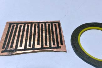
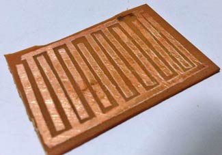
Step 1: Take Copper Clad Board of approx. 2 inch of length and same width and rub it by using the sand paper.
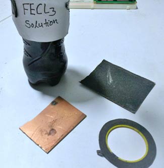
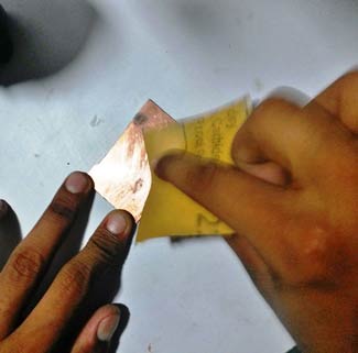
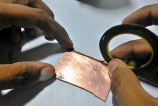
Step 2: Now take the Black tape or Cello tape and stick it to the Clad board as shown in the diagram.
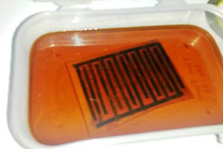
Step 3: We only need copper tracks under the black tape. So we need to remove all the other copper except under the black tape. For this, make Ferric chloride solution (FECL3), by adding 2-3 tea spoon of Ferric chloride in some water. This solution is called Itching Solution. Put the PCB in this solution for approx. half an hour.
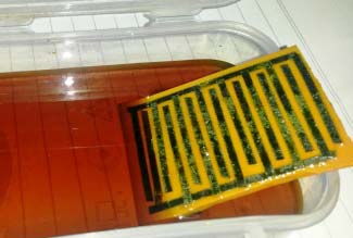
Step 4: Ferric chloride will react and remove the exposed copper and won’t react with the masked copper under the Black tape. Now take out the PCB from the solution without touching the solution and remove the Black tapes.
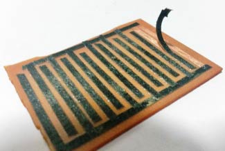
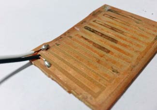
Step 5: Finally solder two wires on the two created coppers ‘tracks’ as shown in the figure and you have your Rain Sensor ready to use.
We also recommend you to go through this article: How to make a PCB at home, before building the Rain Sensor yourself.
Comments
They are two 1uF capacitors
They are two 1uF capacitors connected in series to make it 0.5uF (~0.47uf). Capacitor connected in series are calculated as 1/C= 1/C1 + 1/C2. If you have 0.47uf capacitor, you can use it directly.
Circuit query about automatic rain sensing wipers.
Sir i have followed every instruction given and the circuit is working, but i am getting a problem that the wiper keeps shifting after each oscillation towards the right. Time constant seems to be correct and each cycle is perfectly equal just that the wiper is shifting after each cycle towards right. Please help sir my project is almost over just facing this problem. Waiting for your quick reply. Thank you.
What happend when we not use
What happend when we not use electrolytic capacitor
can u tell me which type of
can u tell me which type of motor is used in the video?
Circuit not working
I am building this for a class in school and am having some issues. First when the power supply is turned on the motor runs constantly. I believe something is not right with the astable multivibrator as the first led does not blink it only glows brightly. The second Led blinks dimly. Any help is greatly appreciated thanks!
Try changing the frequency
Try changing the frequency output of 555 timer by changing the value of R1 and C1.
Now me too geting same prblm.
Now me too geting same prblm...any solutions??
Automatic Rain Sensing Wiper Circuit using 555 Timer IC
Do you have a spreadsheet of the complete parts list with manufacturer, part number and description, ect.?
hi sir , actually i had a
hi sir , actually i had a problem while connecting and lost my PNP transistor , and don't have much time to get a new one can i replace it with NPN and how is that. I'll appreciate your help thnx ^^
Can i see the flowchart for
Can i see the flowchart for this experiment..? I still don't really understand.
about the rotationdl
after Constructing the cct the motor rotate both 360 with speed. what could be the possible problem
Properly configure the 555 IC
Properly configure the 555 IC in astable multivariator mode.
Hi, can i replace the
Hi, can i replace the transistor with an SCR thyristor? Will it work?
(Sunyani Technical University) Electrical engineering project
I have constructed the circuit and it is working but only the DC motor does rotate in clockwise and not anti_clockwise. Is there a way out for me ?
Hey, I've done the circuit
Hey, I've done the circuit and the .motor is rotating in one direction.
So I checked if the astable multivibrator is producing oscillations it seems that the led just glows continuously and is not blinking also led for the comparator is glowing very dim.
What should i do
You need to use the same
You need to use the same value of component as shown in circuit or try to lower down the frequency of Astable multivibrator, check here: 555 Timer Astable Multivibrator Circuit
I've used the components as
I've used the components as specified in the site but the astable multivibrator is not producing oscillations
It worked.Motor is working
It worked.Motor is working in both directions but it's rotating at the same time.what should i do ?
I've made t1=0.53 and t2=0.429 seconds and r1-150ohm ,R2=620 ohm and c1 =1000micro farad
no detection
sir i have connected all the devices as per circuit diagram given but water drops are not detected , i could not find which device is in problem so kindly give u r suggestion on telling which device may have fault
Sir I have used a sg90 servo
Sir I have used a sg90 servo motor. Would it work?
If dc motor ,what type of dc motor should I buy
please don't use water sensor
please don't use water sensor that u purchase fro the shop as it can work only on Audino
how to connect the power
how to connect the power supply i have a 5v and 12v adapter ho to connect to the breDBOARD
circuit not working
Sir, do we need to supply Vcc to all the IC's individually or just to the emitter of PNP transistor?
Automatic rain sensing wiper circuit not working
Both thw leds are glowing together and motor is also rotating in one direction Irrespective of water droplets been present on the senor, I have connected the circuit as specified by the diagram. What are the possible errors/changes needed in the circuit?
Make sure that you have
Make sure that you have connected output of 555 to the inverting terminal of LM358
automatic rain sensing car wiper
unlike your experiment i tried 555 in monostable and l293d also.I want a suggestion can i forcefully stop the wiper for certain angle?will motor get damage?plz help
Sensor problem
I have made the circuit as shown correctly. Ass i am doing this in proteus, i used a dc source and sswitch in place of sensor.The problem is that wether the sensor is on or off the wiper starts working
Here the wiper isn't working
Here the wiper isn't working unless a led glows... Help me..
Is any programming required
Is any programming required for 555 Timer Ic in this circuit
No 555 Timer is an analog IC.
No 555 Timer is an analog IC. A 555 IC cannot be programmed
Is there any micro controller used in this circuit?
Is there any micro controller used in this circuit?
Yes, as Mia stated they are
Yes, as Mia stated they are all ICS. You do not need a MCU or program to make this project work
Proteus is just used to build
Proteus is just used to build the circuit diagram, we cannot do simulation for this circuit in proteus
how we control the speed of motor depending upon rain intensity?
how we control the speed of motor depending upon rain intensity?
Little problem here. The
Little problem here. The motor rotates 360 degrees. I built it with the same components. Help.
check the connections in your
check the connections in your circuit mainly your op-amp section. Your motor is rotating 360 bcs the L293D is not getting the off voltage from op-amp
1.I connected the circuit in
1.I connected the circuit in proteus 8 but with a switch connected with the pnp transistor asuumed to be the sensor bu the circuit runs withou switching on the circuit.
2.How can i implement/connect the circuit in a real car
3. What is the output of the sensor when there is heavy rain and light rain
PLLZ HELP ME AM USING THE CIRCUIT AS MY PROJECT AT COLLEGE
I had built the circuit as
I had built the circuit as per the instruction..i used mini motor and it is not working..the connections are all right..i used an led instead of motor... Wats the prblm in the motor?? Can u please xplain? Its urgent..
The motor is turning in one
The motor is turning in one direction only. Also it is running without applying water in the sensor.
It's most likely because of
It's most likely because of some mistake in your circuit. Give it a good check.
what is the transistor used
what is the transistor used for in the circuit and why is it connected to the h bridge motor driver.
Sir. May I know the function
Sir. May I know the function of the two LED's in the circuit?
good day sir i made it but
good day sir i made it but the motor rotates clockwise then it stops and rotates clockwise again ...what should i do??
I want to do this project but
I want to do this project but i want the motor to continuously turn in one direction. i may also need two motors. So what should i change to make the motor only turn in one direction please?
sir, i have connected all the
sir, i have connected all the components as per the circuit diagram that you have provided but then also i am not getting the output correctly i.e the motor is not getting power to drive itself. Should i use adapter instead of the 9 volt battery?? or any other changes?
My motor is only going in…
My motor is only going in 360° not oscillating. I checked output of 555 timer and it's not a square wave. How do I fix this issue? Did anyone figure out?

HELLO I USED RAIN SENSING CIRCUIT WHICH IS PROVIDED BY YOU I TRIED IT ON BREADBOARD AND IT GLOWS ONLY TWO LED'S WHEN I PRESS BOTTON(USED INSTEAD OF RAIN SENSOR) IT GETS TURNED OFF. I HAVE SEEN YOUR VIDEO AND U USED TWO ELECTROLYTIC CAPACITOR I GOT CONFUSED WITH IT. PLEASE PROVIDE ME A NEW BUIL CIRCUIT WITH A COMPONENT DETAILS IT WILL BE A BIG HELP FOR ME HOPING U WILL REPLYAS SOON AS POSSIBLE.