
In our daily life, we see many types of devices for displaying Text, Images and Graphics. LCDs are one of the most popular Display Device in Electronics and used in mostly all the projects which display some kind of information. There are many types of LCDs used in Electronic Projects. We have already used 16X2 LCD in many of our projects and also used TFT LCD with Arduino. You can find all our 16X2 LCD related project by following this link, including interfacing with 8051, AVR, Arduino and many more.
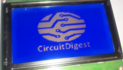
In this tutorial we are going to do Graphic LCD interfacing with 8051 microcontroller. In this project, we will show how to Display an Image on Graphical LCD (GLCD).
Components Required:
- Graphical LCD
- AT89c52 8051 Microcontroller
- 7805 voltage regulator
- 1000uf capacitor
- 10 uF capacitor
- 10K resistor
- 10K POT
- Crystal Oscillator 12 MH
- Connecting wire
- Bread Board
- Burg strips male
- Power supply
- LED
- 220 Ohm resistor
- 1K resistor
Graphical LCD:
A simple 16x2 LCD has 16 pins but Graphical LCD has 20 pin. Pin description is given below as per its datasheet:
| Pin No. | Pin Name | Description | Function |
| 1 | VSS | Ground | 0 Volt |
| 2 | VDD | Power Supply | 5 Volt |
| 3 | V0 | LCD Contrast adjustment | |
| 4 | RS | Command/data Register selection | RS=0: Command Selection and RS=1: Data Selection |
| 5 | R/W | Read/Write Register | R/W=0: Write Selection and R/W=1: Read Selection |
| 6 | E | Enable Signal | |
| 7 | DB0 | Data input/output pin (DB0-DB7) | 8 Bit (DB0-DB7) |
| 8 | DB1 | ||
| 9 | DB2 | ||
| 10 | DB3 | ||
| 11 | DB4 | ||
| 12 | DB5 | ||
| 13 | DB6 | ||
| 14 | DB7 | ||
| 15 | CS1 | Chip Select | CS1 = 1, Chip Select Signal for IC1 |
| 16 | CS2 | Chip Select | CS2 = 1, Chip Select Signal for IC2 |
| 17 | RST | Reset | Reset GLCD |
| 18 | VEE | Negative Voltage for LCD Driver | |
| 19 | A | Back light LED | 5 Volt |
| 20 | K | Back light LED | Ground |
Showing an Image on Graphical LCD using 8051:
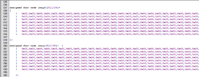
To show an Image on Graphical LCD, first we need to convert that image into Assembly Code, so that 8051 Microcontroller can understand and read it. So we need to follow the below Steps for Converting Image into HEX code:
Step 1: First we need to download a application which convert Image (BMP format) into Assembly Code. So download the BMP2ASM Image Conversion Application from this link, just Right Click on the link and then click Save link as…
Step 2: Then, select the image which you want to display on the Graphical LCD and convert it into BMP, (if it is not in BMP format already) using any application like MS Paint, Photoshop etc. Or you can find many online website for Image format conversion. We have below BMP image, with size 128x64:

Step 3: Now extract the BMP2ASM.zip file, which we have downloaded in Step 1 and open Bmp2asm.exe within it, and select the BMP image.
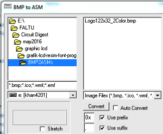
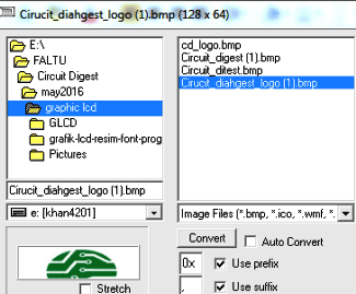
Step 4: Now press “Convert” in BMP2ASM application window.
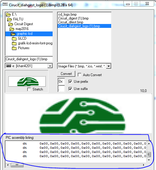
Step 5: Then Copy the generated code and paste in the program of 8051 in Keil uVision. Do some changes and compile the code.
Now your code is ready to upload in 8051 Microcontroller.
Circuit Explanation:

Circuit connections, for Interfacing Graphical LCD to 8051 Microcontroller, is easy and almost same like connecting 16x2 LCD to 8051. But 16x2 LCD has 16 pins and GLCD has 20 pin.
A 10K pot is used for set contrast for GLCD. Control Pins of GLCD RS, R/W and E are directly connected to 89C52 pin number P1.0, P1.1 and P1.2. Chip select pins CS1 and CS2 of LCD are connected to pin P1.3 and P1.4 respectively. Data pins DB0-DB7 are directly connected at PORT P2. A 7805 Voltage regulator is used for regular 5 volt supply. In demonstration Video, I have used Arduino power supply.
Programming Explanation:
First of all, we include required header files in the program and define bits for Control and Data Pins of GLCD.
#include<reg51.h>
#include<intrins.h>
#define lcdport P2

sbit rs=P1^0;
sbit rw=P1^1;
sbit en=P1^2;
sbit cs1=P1^3;
sbit cs2=P1^4;
After it, we have created a delay function.
void delay(int itime)
{
  int i,j;
  for(i=0;i<itime;i++)
  for(j=0;j<125;j++);
}
Function void lcd_disp_on() is used for Turning On the display.
Function void setCursorY(int y) is created for setting the column in GLCD and Function void setCursorX(int x) is created for setting the page on the GLCD. Complete Code file is given in below Code Section.
After setting Column and Page, we have written a function for sending command and data to GLCD.
void lcdprint(char dat,int size)
{
    unsigned int i;
    for(i=0;i<size;i++)
    {
        if(c<64)
        {
            lcdport=dat;
            cs1=1;
    .... .....
    .... .....
In void main() function, we have cleared GLCD and then set Column and Page. After it, send data to LCD by using void lcdprint(char dat,int size) function.
void main()
{
    int x,y;
    P3=0xff;
    while(1)
    {
           lcdclear();
       for(y=0;y<8;y++)
       {
        for(x=0;x<128;x++)
        {
          lcd_disp_on();
          setCursorX(y);
          setCursorY(x);
          lcdprint(image[y][x],x);
        }
       }
    ..... ......
    ..... .......
Flow of Code:
- First when we Power up the system, program clears the GLCD and Turns On the display.
- Then set cursor to Column, from where we want to write the Data.
- Then set cursor to Page, from where we want to write the Data.
- Now program sends Data to the selected location one by one till 128X8 Times. Because a GLCD has 8 pages and 128 Columns.
Complete Project Code
Download the Code file for "Displaying an Image on Graphical LCD using 8051 Microcontroller" from below link, Right Click on link and click Save link as...
Showing_image_on_GLCD_8051.c
Comments
You can use any 128x64
You can use any 128x64 Graphical LCD, its JHD12864E Graphical LCD. You can simulate it in Proteus
JHD12864E Graphical LCD
JHD12864E Graphical LCD Display not found in proteus to simulate. So what can I do now?????
LGM12641BS1R can be used in…
LGM12641BS1R can be used in place of JHD12864E, it is also a pin LCD and fits perfectly when the right pins are matched to the 8051 microcontroller.
WHERE CAN I BUY THIS …
WHERE CAN I BUY THIS (Displaying an Image on Graphical LCD using 8051 Microcontroller)

sir can you tell me the model of glcd and also about the circuit simulator which you had used. i'm using proteus and i am facing trouble in choosing graphical lcd