

In this tutorial we are going to establish a serial communication between two ATMEGA8 microcontrollers. The communication established here is UART (Universal Asynchronous Receiver Transmitter) type. By this serial communication data can be shared between two microcontrollers, which is required in various embedded systems.
Components Required
Hardware: ATMEGA8 (2 pieces), power supply (5v), AVR-ISP PROGRAMMER, 100uF capacitor (connected across power supply), 1KΩ resistor (two pieces), LED , Button.
Software: Atmel studio 6.1, progisp or flash magic.
Circuit Diagram & Explanation

Let us understand the serial communication in AVR microcontrollers. Here ATMEGA sends data to the other ATMEGA in serial. It has other mode of communication but for easy communication we are choosing RS232. The RS232 pin of first ATMEGA8 is connected to RXD pin of second ATMEGA8.
The data communication established is programmed to have:
- Eight data bits
- Two stop bits
- No parity check bit
- Baud rate of 2400 BPS(Bits Per Second)
- Asynchronous communication (No clock share between two ATMEGA8)
So we have two set registers for two ATMEGA8 differently, where one acts as TRANSMITTER and other acts as RECEIVER.
Now for the RS232 interfacing between two ATmega microcontrollers, the following features must be satisfied for the TRANSMITTER and RECEIVER:
1. The TXD pin (data receiving feature) of first controller must be enabled for TRANSMITTER and RXD pin of second controller must be enabled for RECEIVER .
2. Since the communication is serial we need to know whenever the data byte is received, so that we can stop the program until complete byte is received. This is done by enabling a data receive complete interrupt.
3. DATA is transmitted and received to controller in 8bit mode. So two characters will be sent to the controller at a time.
4. There are no parity bits, one stop bit in the data sent by the module.
The above features are set in the controller registers; we are going to discuss them briefly,
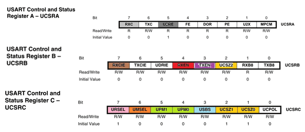
DARK GREY (UDRE): (TRASMITTER SIDE) This bit not set during startup but it is used during working to check whether transmitter is ready to transmit or not. See the program on TRASMITTER SIDE for more details.
LIGHT GREY (RXC): (RECEIVING SIDE) This bit not set during startup but it is used during working to check whether receiver is ready to receive data or not. See the program on RECEIVING SIDE for more details.
VOILET (TXEN): (TRASMITTER SIDE) This bit is set for enabling transmitter pin on TRASMITTER SIDE.
RED (RXEN): (RECEIVING SIDE) This bit represents receive data feature, this bit must be set for the data from the module to be received by the controller, it also enables RXD pin of controller.
BROWN (RXCIE): This bit must be set for getting an interrupt after successful data reception. By enabling this bit we get to know, right after 8 bit data receive. We are not going to use this bit here so it is left alone.
PINK (URSEL): This bit must be set before enable other bits in UCSRC, after setting other needed bits in UCSRC; URSEL must be disabled or put to zero. We are not going to use this bit here so it is left alone.
YELLOW(UCSZ0,UCSZ1,UCSZ2): (RECEIVING SIDE & TRASMITTER SIDE)These three bits are used for selecting the number of data bits we are receiving or sending in a single go.
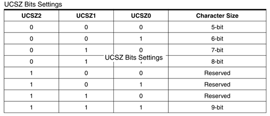
The communication between two ATMEGA is established as eight bit communication. By matching the communication with table we have, UCSZ0, UCSZ1 to one and UCSZ2 to zero.
We have to set these on both receiving and transmitting side.
ORANGE (UMSEL): (RECEIVING SIDE & TRASMITTER SIDE)This bit is set based on whether the system is communicating asynchronously (both use different clock) or synchronously (both use same clock).
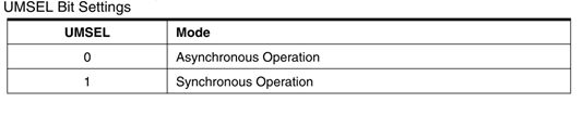
Both the controllers do not share any clock. Since both of them use internal clock of their own. So we need to set UMSEL to 0 in both controllers.
GREEN (UPM1, UPM0): (RECEIVING SIDE & TRASMITTER SIDE) These two bits are adjusted based on bit parity we are using in communication.
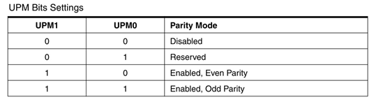
The ATMEGA is programmed to send data with no parity, as the data transmission length is small, we can clearly expect no data loss or error. So we are not setting any parity here. So we set both UPM1, UPM0 to zero or they are left, because all bits are 0 by default..
BLUE (USBS): (RECEIVING SIDE & TRASMITTER SIDE) This bit is used for choosing the number of stop bits we are using during communication.
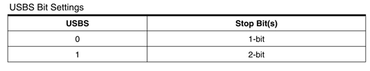
The communication established here is of asynchronous type, so for getting more accurate data transmission and reception, we need to use two stop bits, Hence we set USBS to ‘1’ in both controllers.
The baud rate is set in controller by choosing the appropriate UBRRH.
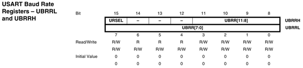
The UBRRH value is chosen by cross referring baud rate and CPU crystal frequency.
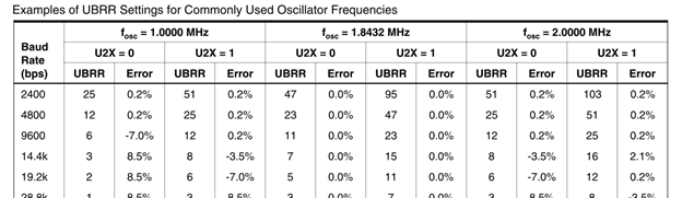
So by cross reference UBRR value is seen as ‘25’, and so the baud rate is set.
As shown in circuit a button is connected on transmitter side. When this button in pressed a eight bit data is sent by TRANSMITTER and this data is received by RECEIVER. On receiving this data successfully it toggles the LED connected to it ON and OFF, which shows successful data transfer between two controller.
Complete Project Code
PROGRAM ON TRANSMITTER SIDE:
#include <avr/io.h>
//header to enable data flow control over pins
#define F_CPU 1000000UL
//telling controller crystal frequency attached
#include <util/delay.h>
//header to enable delay function in program
int main(void)
{
                DDRD |= 1 << PIND1;//pin1 of portD as OUTPUT
                DDRD &= ~(1 << PIND0);//pin0 of portD as INPUT
                PORTD |= 1 << PIND0;
                int UBBRValue = 25;//AS described before setting baud rate
                //Put the upper part of the baud number here (bits 8 to 11)
                UBRRH = (unsigned char) (UBBRValue >> 8);
                //Put the remaining part of the baud number here
                UBRRL = (unsigned char) UBBRValue;
                //Enable the receiver and transmitter
                UCSRB = (1 << RXEN) | (1 << TXEN);
                //Set 2 stop bits and data bit length is 8-bit
                UCSRC = (1 << USBS) | (3 << UCSZ0);
                while (1)
                {
                                if (bit_is_clear(PINC,0))//once button is pressed
                                {
                                                while (! (UCSRA & (1 << UDRE)) );
                                                {
                                                                UDR = 0b11110000;//once transmitter is ready sent eight bit data
                                                }
                                                // Get that data outa here!
                                                _delay_ms(220);
                                }
PROGRAM ON RECEIVER SIDE:
#include <avr/io.h>
#define F_CPU 1000000UL
#include <util/delay.h>
int main(void)
{
                DDRD |= (1 << PIND0);//PORTD pin0 as INPUT
                DDRC=0xFF;//PORTC as OUTPUT
                int UBRR_Value = 25; // 2400 baud rate
                UBRRH = (unsigned char) (UBRR_Value >> 8);
                UBRRL = (unsigned char) UBRR_Value;
                UCSRB = (1 << RXEN) | (1 << TXEN);
                UCSRC = (1 << USBS) | (3 << UCSZ0);
                unsigned char receiveData;
                while (1)
                {
                                while (! (UCSRA & (1 << RXC)) );
                                receiveData = UDR;
                                if (receiveData == 0b11110000)
                                {
                                          PORTC ^= (1 << PINC0);
                                           _delay_ms(220);
                                }
                }
}
Comments
is working, because...
...it writes on both sides the same baud rate...
The reset value of UCSRC suits "8N1" asynchronous setting.
Tip: if you write UCSRC before UBRRH (after reset), you do not need to set URSEL, the reset value is "1", but is cost nothing, do so.
Thank you very much for
Thank you very much for answering me! I forgot the reset value of URSEL is already 1 so no need to set it in code.
Regards
Can you explain me how to
Can you explain me how to display the output in an LCD instead of just glowing the LED.
Two way uart problem
I can send data from one chip 1 to other chip 2, I.e one way communication is done, but can't able to resend data from chip 2 to chip 1. That is two way communication is not happening.
I have enable receiver one transmitter in both chips.
Please help, if possible post a code.
Check if the Tx pin of 2 IC
Check if the Tx pin of 2 IC is connected properly to the Rx pin of the 1st IC. If then the problem is for sure with your code
When I build this code there
When I build this code there is error that lvalue required as left operand of assignment what I do now?There is other statement for that?

UCSRC = (1 << USBS) | (3 << UCSZ0);
How can you write to the UCSRC register when you didn't set the URSEL bit? And you said for URSEL: 'We are not going to use this bit here so it is left alone.', but it is not possible to write to UCSRC register without using that bit because the data is in that case (not using the URSEL) going to be written into UBRRH instead into UCSRC.