

We all know that one of the places where power wastage occurs most in homes and offices is at staircases. We usually turn on light at stairs and leave it in a hurry. In this project we are going to design a stair case lamp which works on battery and only turn on the lights only when someone is present at there. This circuit can be used to save power and it can be used as an emergency backup light.
The circuit works on two conditions - one is presence of light in its location and second is presence of human being, only when these two conditions are met, the controller turns the backup light ON.
These two conditions are tested by two sensors one is LDR and other is PIR Motion sensor module. The LDR senses the presence of light and Motion sensor detects the presence of a human being in its range.
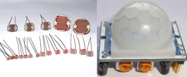
The image on the left side shows the sensor LDR (Light Dependent Resistor) and the picture on the right side show the PIR Sensor or Motion Sensor Module. PIR Sensor is basically an IR (Infrared Receiver). It consists of sensitive IR receives which detects the IR (Infra Red) rays in its region.We know that every living organism emits IR rays and so the human body. Whenever a there is a human in the sensor module region it detects the presence of IR rays.
Whenever a human present in the sensing region of module, the sensor picks up IR changes as human body emits IR rays, so now these changes of IR picked up by module are filtered by electronics in the module and as of signaling the changes in IR, A pulse is generated by the module. This pulse is of duration 5sec by default.
So whenever a human crosses the sensing region of module, it generates a pulse of 5 sec. So presence of human is detected by IR rays by this module.
The motion sensor module will have two pots or presets one of them is to adjust the sensing region of the module and the second is for varying the time of high pulse output on detection of motion. The duration of pulse can be adjusted from few second to few minutes. You can understand more about it by this PIR sensor circuit.
The LDR in this circuit works as a variable resistor. The resistor of the LDR changes based on the light intensity. When the light falling on the LDR is low the resistance of the LDR will be high. When the light falling on LDR is high the resistance across terminals of LDR will be very low compared to low light resistance.
Components Required
Hardware:
ATMEGA32
Power supply (5v),
AVR-ISP PROGRAMMER
100uF capacitor
LED
220Ω, 1KΩ resistors
LDR(Light Dependent Resistor)
100KΩ pot or preset,
Any motion sensor module (HC-SR501)
2WATT LED
TIP122 transistor.
Software:
Atmel studio 6.1
Progisp or flash magic
Circuit Diagram and Working Explanation

As shown in the above automatic staircase lighting circuit, there is no need to connect an external crystal here. Because the ATMEGA works on internal 1MHz, Resistor-Capacitor oscillator on default. Only when the accuracy of clock is needed, as application of high precision counting, external crystal is attaches. When the controller is first bought, it is fused to work on internal crystal by default.
The controller will here will be always checking two things:
- Presence of darkness
- Detection on motion
As we discussed when the light is low the resistance of LDR will be high, now on observation we can tell there is a voltage divider formed by LDR and 100K pot, the middle joint of voltage divider is taken as reference and is connected to PB1 of controller. You can learn more about the working principle of LDR in this LDR circuit.
Now if there is low light the resistance of LDR will be high and so the voltage share in the voltage divider branch changes, Because of high resistance, the voltage across LDR will be higher than that of 100K pot, and because of this the voltage at midpoint drops drastically and this drop is easily sensed by controller. So whenever darkness comes the controller picks up a signal. This signal satisfies the first condition. Understand more about LDRs in this dark detector circuit.
With the presence of motion, there will be pulse at PB0 of controller which is generated by motion sensor module as we discussed earlier.
Once these two conditions are met, the controller is instructed to signal the NPN transistor to drive the power LED.
Complete Project Code
// C program for Automatic Staircase Light
#include <avr/io.h> //header to enable data flow control over pins

#define F_CPU 1000000 //telling controller crystal frequency

#include <util/delay.h> //header to enable delay function in program
int main(void)

{

    DDRB = 0b11111100; //PB0,PB1 are used as inputs and reset are used as outputs

    int x=0; // taking a integer

    while(1)

    {

               if (bit_is_clear(PINB,1)) // In presence of darkness (When there is darkness pin goes low)

               {

                     if (bit_is_set(PINB,0)) //When there is motion (motion sensor gives high output on presence of human being)

                    {

                          x=1; //set x when both conditions are satified

                    }

               }


             if (x==1) //when x is set

            {

                 PORTB |=(1<<PINB2); //trigger transistor to drive power led

                _delay_ms(220); //wait 220ms (can be changed for higher duartion)

                PORTB &=~(1<<PINB2); //turn on transistor trigger

                x=0; // reset x

            }

     }

}
Comments
Yes, you can make this on PCB
Yes, you can make it on PCB board. Design a PCB layout of this circuit and make it on PCB board. Do also share with us.
Thanks
about the project source code
can you give the source code for this project in assembly?
Can you please provide
Can you please provide proteus simulation for this project?
Yes, you can do this with any
Yes, you can do this with any Microcontroller.
i'm having mini project. then
i'm having mini project. then i thought about this project. i'm not an ace student so may i ask is this microC can use for PLC? or do you have any this exact project but build based on plc?
I m not an electronics
I m not an electronics student but i feel it intresting. Will u pls send me a step by step guid to make a PCB and how to assemble the all the items to make a fully working stair lightning.
Thanks
First you need to have PCB
First you need to have PCB layout of the circuit which can be taken from many online software available, for more check this article: How to make a PCB at home?
please am working on
please am working on something like this. but this is actually what i want can you help me
automatic street light controller using pic16f877a to control the led intensity
i need help on my project topic. it is a controller that uses the sensor passive infrared sensor(PIR) and light dependent resistor (LDR). light dependent resistor senses the light intensity(that's day and night) and gives command for the light to come on, but the light intensity should be only 50% bright. then when the PIR detects movement then the light intensity of the LED should be 100% bright. i really need the source code and how to interface each of the component with pic16f877a.
thanks in anticipation
Control Without MC
Dear Concern,
Should i control this without MC if possible then how i do this.
Thanks in advanced.
Yes you can, check our PIR
Yes you can, check our PIR Sensor Based Motion Detector and Dark Detector using LDR Circuit. You can combine them and can connect like when outputs for both (PIR and LDR) are High then only LED will glow. Like using two NPN transistors at LED for both PIR and LDR.
Is this program correct??ⁿ
I have uploaded my program in atmega 32A but after making the same circuit my at mega 32 switches on the led every time, its doesn't take any input from ldr or pit what to do?? Please help urgent.
You may need to adjust Time
You may need to adjust Time delay knob or Distance control knob on PIR sensor. Learn more PIR sensor here.
where am I going to connect
where am I going to connect the capacitor?
related to this project
can you give me the Proteus simulation of this project
Can any ne provide assembly
Can any ne provide assembly code and proteus simulation for this project????
This project cannot be
This project cannot be completely simulated due to the usage of sensors
IEEE Papers for Automatic Staircase Lighting using PIR sensor
Please upload IEEE papers of Automatic Staircase Lighting using PIR sensor.
I need the Arduino Uno
I need the Arduino Uno program for the automatic staircase light using PIR motion sensor
Sir I have encountered errors
Sir I have encountered errors in code can u please tell me what header files are needed to be added in above c program.
Not working. Urgent. Project
Burned the code in ATmega32A.. So the port 9, 6, 7, 8 is not in use By programming port
Have no idea what that is..
Should there be any changes in the circuit diagram if i burn the code into atmega32A
The LED is kept ON as soon i connect the battery

can i make this project on copper board?