
Burglar alarm system is an important part of home security systems. This burglar alarm project is based on PIR sensor, UM3561 and Speaker. PIR sensor used to detect body motion and UM3561 & speaker to produce Police siren after any movement detection.
Required Components
- PIR sensor
- UM3561 IC
- Resistors 220K and 10K
- Transistor BC547
- Speaker 8ohm
- 9V Battery and Battery Snap Connector
- Breadboard Wires
- Breadboard
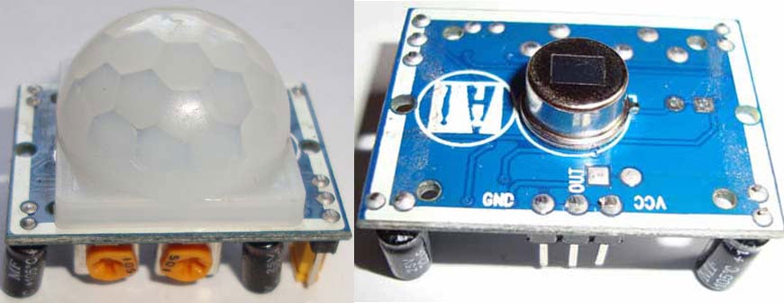
PIR Sensor
PIR sensor is used here to detect the Human body movement, whenever there is any body movement, the voltage at output pin changes. Basically it detects the Change in Heat, and produce output whenever such detection occurs. You can learn more about PIR sensor in this PIR sensor circuit, there are some useful features in PIR sensor like how to change the distance range, how to set Alarm duration etc.
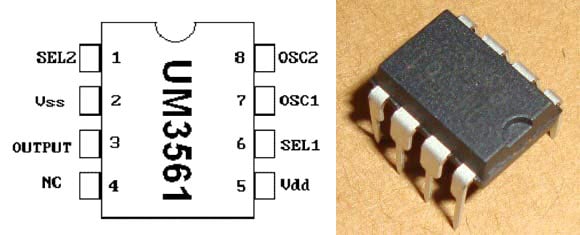
UM3561 IC
UM3561 is a CMOS LSI IC which can generate four types of sound: Police Siren, Ambulance siren, Fire brigade siren and machine gun sound. It is generally used in alarms and toys. It is a 8 pin IC, and only require a external resistor to work. It has inbuilt oscillators and circuitry to produce the sounds. UM3561 works in the range of 3-5 volts, voltage higher than 5V can damage the IC, so if we are using it with other circuit or using a high voltage source, a Zener diode must be connected, to protect the IC. The output generated by the IC is not sufficient to drive a 8ohm small speaker, so to amplify the output of the IC, a transistor must be used at the output (PIN 3).
Pin diagram and Pin description is given below, taken from its Datasheet:
|
Pin No. |
Symbol |
Description |
|
1 |
SEL2 |
Sound Effect Selection Pin No.2 |
|
2 |
Vss |
Ground |
|
3 |
Output |
OUTPUT |
|
4 |
NC |
Internal Testing Pin : Leave Open for Normal Operations |
|
5 |
Vdd |
Positive of Power Supply |
|
6 |
SEL1 |
Sound Effect Selection Pin No.1 |
|
7 |
OSC1 |
External Oscillator Terminal 1 |
|
8 |
OSC2 |
External Oscillator Terminal 2 |
We can play four sound by using its 2 sound Effect selection Pins (SEL 1 and SEL 2), like here in our circuit we kept SEL 1 and SEL 2 open, to produce the Police Siren sound. Below is the table for 4 Playing modes, you can produce whatever sound you want.
|
SEL 1 |
SEL 2 |
Sound Effect |
|
NC |
NC |
Police Siren |
|
Vdd |
NC |
Fire Brigade Siren |
|
Vss |
NC |
Ambulance Siren |
|
X |
Vdd |
Machine Gun |
NC: No Connection
X: Don’t Care
Zener Diode
Zener Diodes are just like the other diodes, with only one difference. All the diodes allow flow of current in only one direction (forward), but Zener diode can allow current in reverse direction if the voltage goes beyond a certain limit. This voltage is called Breakdown Voltage or Zener Knee voltage. So this property of Zener diode protects the UM3561 IC by preventing higher voltage supply to it.

Circuit Diagram and Explanation

This burglar alarm circuit is very simple, whenever PIR sensor detects any human body movement, its OUTPUT pin becomes HIGH, which is connected to UM3561’s Power supply PIN 5. So UM3561 activated and start producing sound with Speaker. As I have stated above that UM3561 doesn’t produce much output to drive a Speaker so we need to connect a Transistor to amplify the current. As long as the PIR sensor OUTPUT pin would be HIGH, the alarm (Speaker) will be continuously ringing, with the sound produced by UM3561. We can set the time duration of Alarm by setting the PIR sensor’s Time delay control regulator, you can set as long as you want.
Here we should note that we didn’t used Zener diode because here in our circuit we are connecting UM3561 with PIR sensor’s output and PIR sensor gives output of approx. 3.3v, which is in range of operating voltage of UM3561, so we do not need any protection from high voltage. Though you can use it for precautionary purpose.
If you want to connect some bigger alarm to the PIR sensor, which works on AC mains 220V, then you need to connect it with Relay. Here is the CIRCUIT , you just need to replace the bulb with AC alarm. There are lot of alarms available in the market.
Comments
if you have report document
if you have report document for this project please asisst.
Thank you so much for posting
Thank you so much for posting these electronics circuits .they really helped us a lot.
I am crazy for circuit
I am crazy for circuit designing and it is Very good Explaination,I like it .(Shukriya Dost).If more suggestion you can give me.I am always here.
Substitute for the IC
Hey, I'm trying to replicate this project, but I can't find the UM3561 IC anywhere, do you have a suggestion for a substitute?
project work
I will like you to help me out with the project materials on the construction of a wireless car security system.
I love your project work
Burglar Alarm Circuit
Hello my name is Majid thank you for making this circuit however i cant seem to make the simulation for it.Can someone send it to me? much appreciated
pls send me the steps in
pls send me the steps in making it, will be very great full, i want to use for my project
DESIGN OF FINGERPRINT BASED BURGLAR DETECTOR USING
Thank you so much for this illustration but please this is a project I am to carryout but it will incorporate fingerprint as its sensing unit. Please I need the circuit diagram and the operation principle, that is, the methodology on how the circuit will work.
Please I am waiting for your reply as quick as possible.
about mechanical parts
can i get the full module of this project
please help me with report
please help me with report document for burglar alarm circuit project.

Thank you so much for posting this project! I made it for my final project in my basic electrical engineering class, and it turned out great.
Thank you.