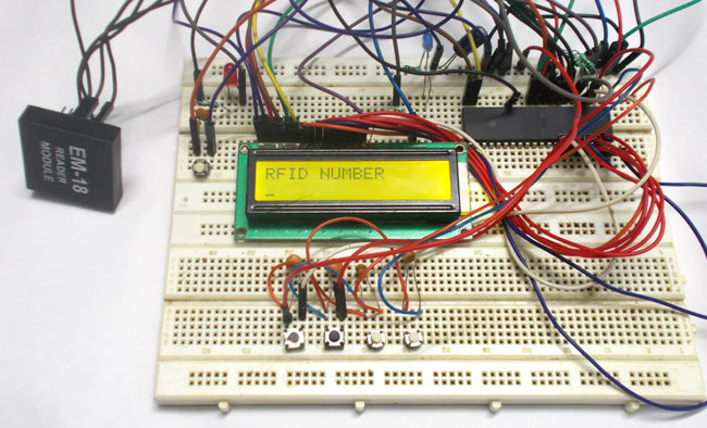
We know in offices, shopping malls and in many other places where only the person with authorization card is allowed to enter the room. These systems use RFID communication system. RFID is used in shopping malls to stop theft as the products are tagged with RFID chip and when a person leaves the building with the RFID chip an alarm is raised automatically. The RFID tag is designed as small as part of sand. The RFID authentication systems are easy to design and are cheap in cost. Some schools and colleges nowadays use RFID based attendance systems.
In this project we are going to design a voting machine which only counts authenticated votes. This is done by using RFID (Radio Frequency Identification) tags. Here we are going to write a program for ATMEGA for allowing only authorized RFID tag holders to vote. (Also check this simple voting machine project)
Components Required
Hardware: ATMEGA32, power supply (5v), AVR-ISP PROGRAMMER, JHD_162ALCD (16x2LCD), 100uF capacitor (connected across power supply), button (five pieces), 10KΩ resistor (five pieces), 100nF capacitor (five pieces), LED (two pieces), EM-18(RFID reader module).
Software: Atmel studio 6.1, progisp or flash magic.
Circuit Diagram and Explanation
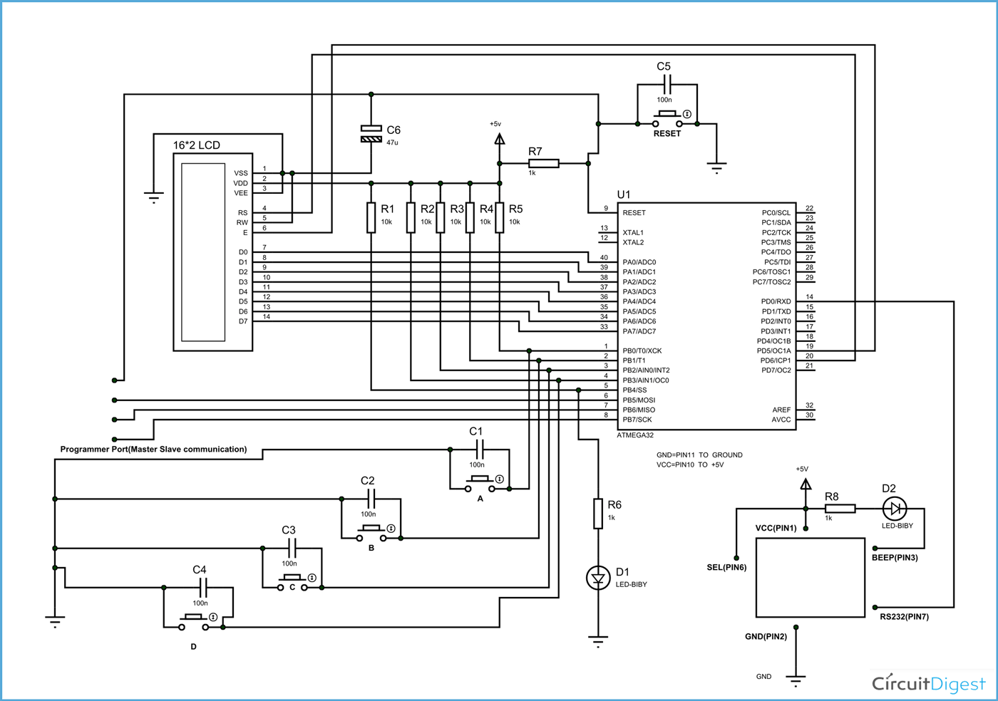
In circuit PORTA of ATMEGA32 is connected to data port of LCD. Here one should remember to disable the JTAG communication in PORTC to ATMEGA by changing the fuse bytes, if one wants to use the PORTC as a normal communication port. In 16x2 LCD there are 16 pins overall if there is a black light, if there is no back light there will be 14 pins. One can power or leave the back light pins. Now in the 14 pins there are 8 data pins (7-14 or D0-D7), 2 power supply pins (1&2 or VSS&VDD or gnd&+5v), 3rd pin for contrast control (VEE-controls how thick the characters should be shown), 3 control pins (RS&RW&E)
In the circuit, you can observe that I have only took two control pins, this give the flexibility of better understanding, the contrast bit and READ/WRITE are not often used so they can be shorted to ground. This puts LCD in highest contrast and read mode. We just need to control ENABLE and RS pins to send characters and data accordingly.
The connections which are done for LCD are given below:
PIN1 or VSS to ground
PIN2 or VDD or VCC to +5v power
PIN3 or VEE to ground (gives maximum contrast best for a beginner)
PIN4 or RS (Register Selection) to PD6 of uC
PIN5 or RW (Read/Write) to ground (puts LCD in read mode eases the communication for user)
PIN6 or E (Enable) to PD5 of uC
PIN7 or D0 to PA0 of uC
PIN8 or D1 to PA1 of uC
PIN9 or D2 to PA2 of uC
PIN10 or D3 to PA3 of uC
PIN11 or D4 to PA4 of uC
PIN12 or D5 to PA5 of uC
PIN13 or D6 to PA6 of uC
PIN14 or D7 to PA7 of uC
In the circuit, you can see we have used 8bit communication (D0-D7). However this is not a compulsory and we can use 4bit communication (D4-D7) but with 4 bit communication program becomes a bit complex, so I preferred 8 bit communication.
So from mere observation of above table we are connecting 10 pins of LCD to controller in which 8 pins are data pins and 2 pins for control.
Before moving ahead, we need to understand about the serial communication. The RFID module here sends data to the controller in serial. It has other mode of communication but for easy communication we are choosing RS232. The RS232 pin of module is connected to RXD pin of ATMEGA.
The data sent by the RFID module goes as:

Now for the RFID module interface, the following features are required:
1. The RXD pin (data receiving feature) of controller must be enabled.
2. Since the communication is serial we need to know whenever the data bye is received, so that we can stop the program until complete byte is received. This is done by enabling a data receive complete interrupt.
3. RFID sends data to controller in 8bit mode. So two characters will be sent to the controller at a time. This is shown in block of figure3
4. From figure3, there are no parity bits, one stop bit in the data sent by the module.
The above features are set in the controller registers; we are going to discuss them briefly,


RED (RXEN): This bit represents receive data feature, this bit must be set for the data from the module to be received by the controller, it also enables RXD pin of controller.
BROWN (RXCIE): This bit must be set for getting an interrupt after successful data reception. By enabling this bit we get to know, right after 8 bit data receive.
PINK (URSEL): This bit must be set before enable other bits in UCSRC, after setting other needed bits in UCSRC; URSEL must be disabled or put to zero.
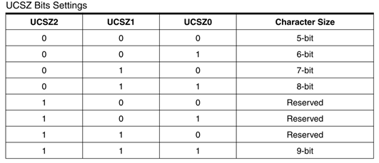
YELLOW(UCSZ0,UCSZ1,UCSZ2):These three bits are used for selecting the number of data bits we are receiving or sending in a single go.

Since the data sent by RFID module is 8bit data type (FIGURE3), we have to set UCSZ0, UCSZ1 to one and UCSZ2 to zero.
ORANGE (UMSEL): This bit is set based on whether the system is communicating asynchronously (both use different clock) or synchronously (both use same clock),

Since module and controller use different clock, this bit must be set to zero or left alone as they are all set to zero by default.
GREEN (UPM1, UPM0): These two bits are adjusted based on bit parity we are using in communication.

Since RFID module sends data with no parity (FIGURE3), we have set both UPM1, UPM0 to zero or they can be left alone as all bits in any registers are set to zero by default.
BLUE (USBS): This bit is used for choosing the number of stop bits we are using during communication.

Since RFID module sends data with one stop bit (figure3), we just have to leave USBS bit alone.
Now at last we need to set the baud rate, from figure3 it is clear that the RFID module sends data to controller with a baud rate of 9600bps (bits per second).
The baud rate is set in controller by choosing the appropriate UBRRH,

The UBRRH value is chosen by cross referring baud rate and CPU crystal frequency,
So by cross reference UBRR value is seen as ‘6’, and so the baud rate is set.

There are five buttons present here, four for incrementing the votes of candidates and fifth is for resetting the candidates’ votes to zero. The capacitors present here is for nullifying the bouncing effect of buttons. If they are removed the controller might count more than one each time the button is pressed.
The resistors connected for pins are for limiting the current, when the button is pressed to pull down the pin to the ground. Whenever a button is pressed, The corresponding pin of controller gets pulled down to ground and thus the controller recognizes that certain button is pressed and corresponding action to be taken, it may be incrementing the candidate votes or resetting of votes depending on button pressed.
When the button representing a corresponding person is pressed, the controller picks it and increments the corresponding person number inside its memory after increment it shows the corresponding persons score on the 16x2 LCD display.
The working of voting machine is best explained in step by step of C code given below:
Code Explanation
#include <avr/io.h> //header to enable data flow control over pins
#define F_CPU 1000000 //telling controller crystal frequency attached
#include <util/delay.h> //header to enable delay function in program
#define E 5 //giving name “enable” to 5th pin of PORTD, since it Is connected to LCD enable pin
#define RS 6 //giving name “registerselection” to 6th pin of PORTD, since is connected to LCD RS pin
void send_a_command(unsigned char command);
void send_a_character(unsigned char character);
void send_a_string(char *string_of_characters);
int main(void)
{
DDRA = 0xFF; //putting porta as output pins
DDRD = 0b11111110;
_delay_ms(50);//giving delay of 50ms
DDRB = 0b11110000;//Taking some portB pins as input.
UCSRB |=(1<<RXEN)|(1<<RXCIE);
// enabling data receive complete interrupt,enabling data receive pin
UCSRC |=(1<<URSEL)|(1<<UCSZ0)|(1<<UCSZ1);
//changing other bits by first setting URSEL, setting for 8 bit communication
UCSRC &=~(1<<UMSEL); //using asynchronous communication
UBRRH &=~(1<<URSEL);
UBRRL=6;//setting the baud rate
int16_t VOTEA = 0;//person1 votes storing memory
char A [4];//person1 votes displaying character on LCD
int16_t VOTEB = 0; ;//person2 votes storing memory
char B [4];//person2 votes displaying character on LCD
int16_t VOTEC = 0; ;//person3 votes storing memory
char C [4];//person3 votes displaying character on LCD
int16_t VOTED = 0; ;//person4 votes storing memory
char D [4];/ /person4 votes displaying character on LCD
//The following contains ID of tags, these must be changed for different tags, These must be updated for the project to work
//After dumping the program in the controller one must take the cards which must be authorized and get the tags ID , these are obtained by placing the tag near RFID module and the ID will be shown on the screen. After getting the IDs, the program must be updated by replacing the below ID numbers with new ID numbers.
|
char ADMIT [5][4]={{(0x97),(0xa1),(0x90),(0x92)},{(0x97),(0xa1),(0x90),(0x93)},{(0x97),(0xa1),(0x90),(0x94)},{(0x97),(0xa1),(0x90),(0x95)},{(0x97),(0xa1),(0x90),(0x96)}}; |
Now in above we are authorizing only five cards, these can be changed to any number,
For example consider the default program is dumped in the controller, get the cards which should be authorized place one after other near module, you will get the ID for each one as xxxxxxxx (907a4F87),
If there are 7 tags we have, then we will have 7 eight bit ID.
|
//now for seven cards it goes as //char ADMIT[7][4]={{(0x90),(0x7a),(0x4F),(0x87)},[},{},{},{},{},{}} //Now once all the IDs are written, those ID tags are considered as authorized |
Int16_t COUNTA = 0;//allotting memory for storing ID send by module
char SHOWA [4];// allotting memory for showing the ID send by module
int i=0;
int vote =0;
int k =0;
send_a_command(0x01); //Clear Screen 0x01 = 00000001
_delay_ms(50);
send_a_command(0x38);//telling lcd we are using 8bit command /data mode
_delay_ms(50);
send_a_command(0b00001111);//LCD SCREEN ON and courser blinking
char MEM[4];//allotting memory to store complete ID of tag
send_a_string ("RFID NUMBER");//sending string
send_a_command(0x80 + 0x40 + 0);//moving courser to second line
while(1)
{
while(!(UCSRA&(1<<RXC)));//wait till first eight bit data is received
{
}
COUNTA=UDR;//UDR stores the eight bit data received and is taken into an integer.
MEM[0]=COUNTA;//first two characters are updated to memory
itoa(COUNTA,SHOWA,16); //command for putting variable number in LCD(variable number, in which character to replace, which base is variable(ten here as we are counting number in base10))
send_a_string(SHOWA); //telling the display to show character(replaced by variable number) of second person after positioning the courser on LCD
while(!(UCSRA&(1<<RXC)));//wait till second eight bit data is received
{
}
COUNTA=UDR;
itoa(COUNTA,SHOWA,16);
send_a_string(SHOWA);
MEM[1]=COUNTA; //third and fourth characters are updated to memory
while(!(UCSRA&(1<<RXC))); //wait till third eight bit data is received
{
}
COUNTA=UDR;
itoa(COUNTA,SHOWA,16);
send_a_string(SHOWA);
MEM[2]=COUNTA;// fifth and sixth characters are updated to memory
while(!(UCSRA&(1<<RXC))); //wait till fourth eight bit data is received
{
}
COUNTA=UDR;
itoa(COUNTA,SHOWA,16);
send_a_string(SHOWA);
MEM[3]=COUNTA;// seventh and eight characters are updated to memory
send_a_string(" ");
send_a_command(0x80 + 0x40 + 0);
UCSRB &=~(1<<RXEN);//disabling the receive data until the tag ID is checked for authorization
for (i=0;i<5;i++)
{
if ((MEM[0]==ADMIT[i][0])&(MEM[1]==ADMIT[i][1])&(MEM[2]==ADMIT[i][2])&(MEM[3]==ADMIT[i][3]))
{ //checking for authorization buy comparing two characters at a time with the characters in the memory
PORTB|=(1<<PINB4);//if authorized turn the LED ON
vote=1;//if authorized set VOTE
}
}
if (vote==0)//authorization failed if vote is not set
{
UCSRB |=(1<<RXEN);//start receiving data from module
}
while (vote==1)//do this loop until voted ,if authorized
{
send_a_command(0x80 + 0);//go to position zero on line1
send_a_string ("VOTE NOW ");//displaying string
if (bit_is_clear(PINB,0)) //when button one is pressed
{
VOTEA++; //increment the vote memory of first person by one
vote=0;//letting while loop go after voting
}
if (bit_is_clear(PINB,1 ))//when button 2 is pressed
{
VOTEB++;// increment the vote memory of 2nd person by one
vote=0;
}
if (bit_is_clear(PINB,2))//when button 3 is pressed
{
VOTEC++;// increment the vote memory of 3rd person by one
vote=0;
}
if (bit_is_clear(PINB,3)) //when button 4 is pressed
{
VOTED++;// increment the vote memory of 4th person by one
vote=0;
}
if (vote==0)//cleared after vote received
{
send_a_command(0x80 + 0);//move to position zero of line1
send_a_string ("THANK U FOR VOTE");//display string
for (k=0;k<10;k++)
{
_delay_ms(220);
}
PORTB&=~(1<<PINB4);//turn off vote allow LED
send_a_command(0x01);
send_a_command(0x80 + 0); //displaying votes of all four persons
send_a_string ("A=");
send_a_command(0x80 + 2);
itoa(VOTEA,A,10);
send_a_string(A);
send_a_command(0x80 + 8);
send_a_string ("B=");
send_a_command(0x80 + 10);
itoa(VOTEB,B,10);
send_a_string(B);
send_a_command(0x80 + 0x40 + 0);
send_a_string ("C=");
send_a_command(0x80 + 0x40 + 2);
itoa(VOTEC,C,10);
send_a_string(C);
send_a_command(0x80 + 0x40 + 8);
send_a_string ("D=");
send_a_command(0x80 + 0x40 + 10);
itoa(VOTED,D,10);
send_a_string(D);
send_a_command(0x80 + 0x40 + 16);
for (k=0;k<25;k++)
{
_delay_ms(220);
}
UCSRB |=(1<<RXEN);//enabling receive data pin after vote
send_a_command(0x01);
send_a_command(0x80 + 0);// moving to zero position
send_a_string ("RFID NUMBER");//send a string
send_a_command(0x80 + 0x40 + 0);
}
}
void send_a_command(unsigned char command)
{
PORTA = command;
PORTD &= ~ (1<<RS); //putting 0 in RS to tell lcd we are sending command
PORTD |= 1<<E; //telling lcd to receive command /data at the port
_delay_ms(50);
PORTD &= ~1<<E;//telling lcd we completed sending data
PORTA= 0;
}
void send_a_character(unsigned char character)
{
PORTA= character;
PORTD |= 1<<RS;//telling LCD we are sending data not commands
PORTD |= 1<<E;//telling LCD to start receiving command/data
_delay_ms(50);
PORTD &= ~1<<E;//telling lcd we completed sending data/command
PORTA = 0;
}
void send_a_string(char *string_of_characters)
{
while(*string_of_characters > 0)
{
send_a_character(*string_of_characters++);
}
}
Complete Project Code
/*

RFID Based Electronic Voting Machine

 */

#include <avr/io.h>

#define F_CPU 1000000

#include <util/delay.h>

#include <stdlib.h>
#define enable            5

#define registerselection 6
void send_a_command(unsigned char command);

void send_a_character(unsigned char character);

void send_a_string(char *string_of_characters);
int main(void)

{

    DDRA = 0xFF;

    DDRB = 0b11110000;


    DDRD = 0b11111110;

    _delay_ms(50);


    UCSRB |=(1<<RXEN)|(1<<RXCIE);

    UCSRC |=(1<<URSEL)|(1<<UCSZ0)|(1<<UCSZ1);

    UCSRC &=~(1<<UMSEL);

    UBRRH &=~(1<<URSEL);

    UBRRL=6;


    char ADMIT [5][4]={{(0x97),(0xa1),(0x90),(0x92)},{(0x97),(0xa1),(0x90),(0x93)},{(0x97),(0xa1),(0x90),(0x94)},{(0x97),(0xa1),(0x90),(0x95)},{(0x97),(0xa1),(0x90),(0x96)}};

    int16_t COUNTA = 0;

    char SHOWA [4];

    int i=0;

    int vote =0;

    int k =0;


    int16_t VOTEA = 0;

    char A [4];

    int16_t VOTEB = 0;

    char B [4];

    int16_t VOTEC = 0;

    char C [4];

    int16_t VOTED = 0;

    char D [4];
    send_a_command(0x01); //Clear Screen 0x01 = 00000001

    _delay_ms(50);

    send_a_command(0x38);

    _delay_ms(50);

    send_a_command(0b00001111);

    _delay_ms(50);

    char MEM[4];

    send_a_string ("RFID NUMBER");

    send_a_command(0x80 + 0x40 + 0);

    while(1)

    {

        while(!(UCSRA&(1<<RXC)));

        {


        }

        COUNTA=UDR;

        MEM[0]=COUNTA;

        itoa(COUNTA,SHOWA,16);

        send_a_string(SHOWA);


        while(!(UCSRA&(1<<RXC)));

        {


        }

        COUNTA=UDR;

        itoa(COUNTA,SHOWA,16);

        send_a_string(SHOWA);

        MEM[1]=COUNTA;


        while(!(UCSRA&(1<<RXC)));

        {


        }

        COUNTA=UDR;

        itoa(COUNTA,SHOWA,16);

        send_a_string(SHOWA);

        MEM[2]=COUNTA;

        while(!(UCSRA&(1<<RXC)));

        {


        }

        COUNTA=UDR;

        itoa(COUNTA,SHOWA,16);

        send_a_string(SHOWA);

        MEM[3]=COUNTA;


        send_a_string("        ");


        send_a_command(0x80 + 0x40 + 0);


        UCSRB &=~(1<<RXEN);

        for (i=0;i<5;i++)

        {


            if ((MEM[0]==ADMIT[i][0])&(MEM[1]==ADMIT[i][1])&(MEM[2]==ADMIT[i][2])&(MEM[3]==ADMIT[i][3]))

            {

                PORTB|=(1<<PINB4);

                vote=1;

            }

        }

        if (vote==0)

        {

            UCSRB |=(1<<RXEN);

        }

        while (vote==1)

        {

            send_a_command(0x80 + 0);

            send_a_string ("VOTE NOW       ");

            if (bit_is_clear(PINB,0))

            {

                VOTEA++;

                vote=0;

            }

            if (bit_is_clear(PINB,1))

            {

                VOTEB++;

                vote=0;

            }

            if (bit_is_clear(PINB,2))

            {

                VOTEC++;

                vote=0;

            }

            if (bit_is_clear(PINB,3))

            {

                VOTED++;

                vote=0;

            }


            if (vote==0)

            {

                send_a_command(0x80 + 0);

                send_a_string ("THANK U FOR VOTE");

                for (k=0;k<10;k++)

                {

                    _delay_ms(220);

                }

                PORTB&=~(1<<PINB4);

                send_a_command(0x01);

                send_a_command(0x80 + 0);

                send_a_string ("A=");

                send_a_command(0x80 + 2);

                itoa(VOTEA,A,10);

                send_a_string(A);

                send_a_command(0x80 + 8);


                send_a_string ("B=");

                send_a_command(0x80 + 10);

                itoa(VOTEB,B,10);

                send_a_string(B);

                send_a_command(0x80 + 0x40 + 0);


                send_a_string ("C=");

                send_a_command(0x80 + 0x40 + 2);

                itoa(VOTEC,C,10);

                send_a_string(C);

                send_a_command(0x80 + 0x40 + 8);


                send_a_string ("D=");

                send_a_command(0x80 + 0x40 + 10);

                itoa(VOTED,D,10);

                send_a_string(D);

                send_a_command(0x80 + 0x40 + 16);

                for (k=0;k<25;k++)

                {

                    _delay_ms(220);

                }

                    UCSRB |=(1<<RXEN);

                send_a_command(0x01);

                send_a_command(0x80 + 0);

                send_a_string ("RFID NUMBER");

                send_a_command(0x80 + 0x40 + 0);

            }

        }

    }

}
void send_a_command(unsigned char command)

{

    PORTA = command;

    PORTD &= ~ (1<<registerselection);

    PORTD |= 1<<enable;

    _delay_ms(20);

    PORTD &= ~1<<enable;

    PORTA = 0;

}
void send_a_character(unsigned char character)

{

    PORTA = character;

    PORTD |= 1<<registerselection;

    PORTD |= 1<<enable;

    _delay_ms(20);

    PORTD &= ~1<<enable;

    PORTA = 0;

}

void send_a_string(char *string_of_characters)

{

    while(*string_of_characters > 0)

    {

        send_a_character(*string_of_characters++);

    }

}
Comments
These RFID cards are readily
These RFID cards are readily available in Market or online stores.
Yes you can buy them online.
Yes you can buy them online. I prefer EBAYINDIA , if you are from INDIA
RFID reading error
sir. when i showing an RFID Tag to EM-18 .the 16x2 LCD display displaying a code then i showing the same tag again it dispalying a different code...
Nice effort from your team I
Nice effort from your team I must commend
regarding atmega
Does we have to provide external crystal to atmega
in circuit diagram what is
in circuit diagram what is programmable port(master slave communication) and where it have to connect
How can code sent in this…
How can code sent in this project explain.


Can you help me figure out what are the different code above exactly and how in which language and to use them while the implementation please i need help wanna make this project for the clg exam