

IR remote is one of the simplest, easiest, and cheapest ways to transfer data wirelessly. The range of this device is not that much but that's exactly why it is perfect for simple Home Automation projects, TV Remotes, and others. Because of such a project, I had to interface an IR remote with a PIC microcontroller. My initial objective was to find a library for IR remote online. But after searching quite a bit, I was unable to find a simple library that does the job. This is why I had to go the hard way and make my own library for IR remote that is supported by a PIC microcontroller. In this tutorial, I want to share with you the engineering and design process that I had to go through and the challenges that I had to face before I was able to create my own IR remote Decoder library for a PIC microcontroller. We also build IR Signal Decoder using STM8S Microcontroller.
Previously, we used IR remote and IR receiver to build many useful applications like:
- IR Remote Controlled TRIAC Dimmer Circuit
- IR Remote Controlled Home Automation using Arduino
- IR Remote Controlled Home Automation using PIC Microcontroller
- Cell Phone Controlled AC using Arduino and Bluetooth
- Home Automation Project Based on an IR Remote Controller
What are the Different IR Protocols and How Can you Decode It?
There are various types of IR protocols out there but among them, the most common ones are NEC Remote Protocol and RC5 Remote Protocol. Today, we will take NEC as an example. To avoid interference, the NEC code uses a carrier frequency of 38KHz. The actual data is modulated using this 38KHz modulating frequency. The image below will give you a better idea of the process.
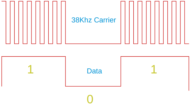
The image you see above is a very rational example of how the decoded data looks, but it’s simple that way. Now, let’s see how it looks under my oscilloscope.
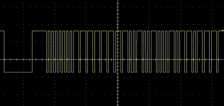
When a button on the remote is pressed, the IR Blaster sends a stream of data the receiver receives and processes it. The image you see above is the actual decoded data by the IR sensor. It is a special piece of IC that can remove the carrier signal and decode the data. We will talk about this IC later in the article. For now, let’s concentrate on the actual Received data.
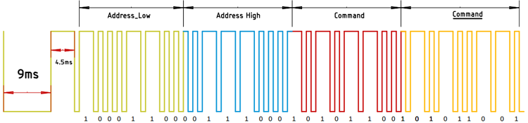
In the image above, you see an example of data that is received by the sensor. The NEC protocol starts with a big 9ms sturt pulse followed by a 4.5ms inverted pulse. By detecting the big pulse and the inverted pulse we can be very sure what comes next is our data. The NEC protocol uses pulse distance encoding to encode the data. Each pulse in the series is 562.5us long, with a carrier frequency of 38Khz. For logic 0, a single 562.5us high pulse followed by a 562.5us low pulse. This produces a total transmission time of 1125us. For logic 1, a 562.5us high pulse followed by 1687 us (562.5 x 3) low pulse sums up to a total transmission time of 2250us. Now, you know quite a lot about the IR sensor and its data transmission process.
TSOP38238 IR Receiver:
The TSOP3823 receiver is a special receiver IC that can remove the carrier frequency and decodes the actual data it doses with the help of an internal PIN diode and a preamplifier combination that are assembled on an epoxy package that contains the IR filter. The internal block diagram is shown below.
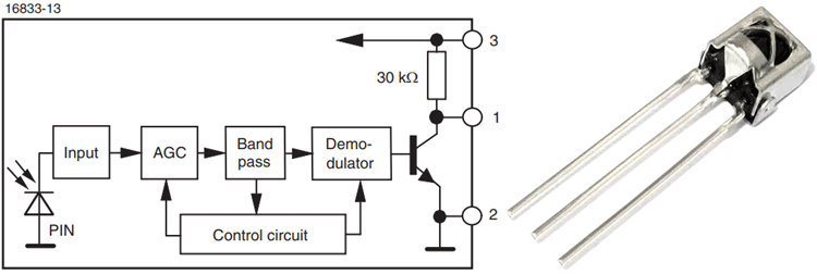
When the button of the remote is pressed, the IR LED inside the remote emits infrared light that is modulated at 38KHz (for NEC protocol). The light is modulated because the Sun also emits infrared light and the sunlight can interfere with the transmitted data by modulating it so, we can minimize such problems. Upon receiving the data, the microcontroller or the processing device decodes it and generates the final output.
Components Required to Build IR Decoder Test Circuit
The list of components required for this project is given below. To build this project, I have used pretty generic components and you can find them in your local hobby store.
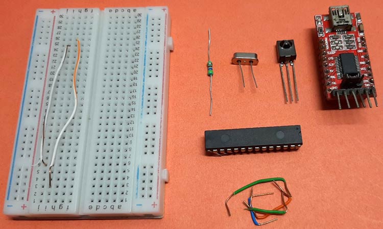
- PIC16F886 Microcontroller - 1
- Resistor 4.7K - 1
- TSOP1838 IR Receiver - 1
- Breadboard - 1
- FTDI UART Module - 1
- Jumper Wires - 1
- NEC Remote
PIC Microcontroller Based IR Decoder - Schematic
The schematic shown below is used to construct the hardware section for the PIC Microcontroller Based IR Decoder Circuit.

The heart of the project is the PIC16F886 microcontroller clocked at 16MHz the FTDI UART module in the circuit is used for debugging the data and sending the data over serial. A pullup resistor is used to pull the MCLR pin of the microcontroller to VCC. The value for the resistor can be between 4.7K- 10K. Finally, I have used a TSOP1838 sensor as we will be using a remote that has a 38KHz carrier frequency.
Programming the PIC16F886 Microcontroller to Decode IR Remote Data
The complete code for the PIC microcontroller-based IR remote decoder can be found at the bottom of this page. For this article, we have used the MPLAB X IDE to compile and upload the code. A complete breakdown and description of the code is given below.
We start by including all the #pragma configuration settings. These #pragma settings have their sector of flash memory that's outside the program code. These settings are applied as soon as the PIC gets power, regardless of where they are written in the code. This is important because if the code runs without these settings, you will get an error output.
In the microcontroller, some settings select the clock source and convert it to the clock for your PIC. This can't be done in the program code because the clock has to be configured correctly before your code can run.
#pragma config FOSC = HS // Oscillator Selection bits (HS oscillator: High-speed crystal/resonator on RA6/OSC2/CLKOUT and RA7/OSC1/CLKIN)
#pragma config WDTE = OFF // Watchdog Timer Enable bit (WDT disabled)
#pragma config PWRTE = OFF // Power-up Timer Enable bit (PWRT disabled)
#pragma config MCLRE = OFF // RE3/MCLR pin function select bit (RE3/MCLR pin function is MCLR)
#pragma config CP = OFF // Code Protection bit (Program memory code protection is disabled)
#pragma config CPD = OFF  // Data Code Protection bit (Data memory code protection is disabled)
#pragma config BOREN = ON // Brown Out Reset Selection bits (BOR enabled)
#pragma config IESO = OFF // Internal External Switchover bit (Internal/External Switchover mode is enabled)
#pragma config FCMEN = OFF // Fail-Safe Clock Monitor Enabled bit (Fail-Safe Clock Monitor is enabled)
#pragma config LVP = OFF // Low Voltage Programming Enable bit (RB3/PGM pin has PGM function, low voltage programming enabled)
// CONFIG2
#pragma config BOR4V = BOR40V // Brown-out Reset Selection bit (Brown-out Reset set to 4.0V)
#pragma config WRT = OFF // Flash Program Memory Self Write Enable bits (Write protection off)
Next, we have defined _XTAL_FREQ macro. This is important to put it at the top otherwise many built-in macro like _delay_ms(), _delay_us() will not work.
#define _XTAL_FREQ 16000000 //16mhz crystal oscillator
Next, we include all the required libraries here <xc.h>, <pic16f886.h> and <stdio.h> library comes with MPLAB X IDE, but the library for “uart.h” and “IRlib.h” we custom build these two for this tutorial. We will discuss it later in the article.
#include <xc.h> // XC library has all the necessary functions and definitions.
#include <stdio.h> //We have Included the stdio library because we are using printf for serial.’
#include <pic16f886.h> //
#include "uart.h" // Custom UART Library
#include "IRlib.h" // Custom IR library
Next, we have defined another set of macros that will help us to understand the code clearly. These macros define interrupts, global interrupts, peripherals, interrupts, and more.
#define GLOBAL_INTERRUPT INTCONbits.GIE  //1 = Enables all unmasked interrupts  0 = Disables all interrupts
#define PERIPHERAL_INTERRUPT INTCONbits.PEIE //1 = Enables all unmasked peripheral interrupts 0 = Disables all peripheral interrupts
#define TIMER0_OVERFLOW_INTERRUPT  INTCONbits.T0IE //1 = Enables the Timer0 interrupt 0 = Disables the Timer0 interrupt
#define PRESCALER_ASSIGNMENT OPTION_REGbits.PSA // 1 = Prescaler is assigned to the WDT 0 = Prescaler is assigned to the Timer0 module

#define ENABLE 1
#define DISABLE 0
#define OUTPUT 0
#define INPUT 1
#define TO_WDT 1
#define ENABLE_LOG 1
#define DISABLE_LOG 0
Next, we have declared some functions, the INTERRUPTS_Init() function enables all the necessary interrupts that are required by the code. The assign_prescaler() functions assign the prescales required by the code and finally, finally, we have the init() function which combines the above to and also enables the serial monitor with serialBegin(9600, _XTAL_FREQ); function.
/* Enables all required Interrupts
 * Timer0 Overflow Interrupt is used to measure
 * the incoming pulse duration from the TSOP Sensor
 */
void INTERRUPTS_Init() {
    GLOBAL_INTERRUPT = ENABLE; // ENable Global Interrupt
    PERIPHERAL_INTERRUPT = ENABLE; // Enable Peripheral Interrupt
    TIMER0_OVERFLOW_INTERRUPT = ENABLE; // Enable Timer0 Overflow
}
/* The Prescaler inside the PIC16f886 microcontroller
 * is either assigned to Watchdog timer or it's assigned
 * to the TIMER0: For this code, we have set it to WDT
 * */
void assign_prescaler() {
    PRESCALER_ASSIGNMENT = TO_WDT;
}
void init() {
    serialBegin(9600, _XTAL_FREQ); // Enable Serial with 9600 Baud )
    INTERRUPTS_Init(); // Enable all Interrupts
    assign_prescaler(); // assign prescaler
}
Next, we have our main() function, in the main function, we call the init() function as we have declared it on the top, next we call the ir_init() function which comes from the IR library. Next, we use the printf() function from the studio.h library to check if printf is working or not, if it's working, then we get the message printed out in the serial monitor window. Next, we check the IR_SENSOR_PIN if it's high or low. If low, we check if any data from the remote is received or not.
void main(void) {
    init(); // we call the init() function
    ir_init(); // we call the iR_init function.
    printf("System Initialized \n"); // First print statement for debugging

    while (1) {
        if (IR_SENSOR_PIN == 0) {

            ir_result(ENABLE_LOG);
        }
    }
    return;
}
As this part is done, we can move on and look inside the libraries.
Understand the UART library:
The UART library consists of the uart.h and uart.c file to enable UART, you need to include both of them in your project file and then you need to call its functions. Inside the uart.h library there is not much. We have included necessary libraries and function prototypes inside the UART library.
void putch(char data); // putch() function prototype
void serialBegin(unsigned int baudRate,long freq); //serialBegin() function prototype
Now, we have our “uart.c” file, inside this .c file all the major processing takes place. We start by including the “uart. h” library, next we define all the necessary bit positions that are required to enable the UART. Next, we declare the putch() function. For microchip compilers, putch() function is a special function when printf() is called the compiler knows to redirect it to putch() and that's how we can enable printf() for the xc8 compiler. In the next part, we have our serialBegin() function that enables the serial. The code inside this section is very simple. First, we make the TX port as output and the RX port as input. We configured the TXSTA bit which enables the UART asynchronous mode. Next, we configure the Receive Status and Control Register. In this function, we enable the serial and we also enable the Single Receive Enable bit. For a particular baud rate, we need to calculate the SPBRG register value. For calculation, please refers to the datasheet of the PIC16F886 microcontroller.
#include <xc.h>
#include <pic16f886.h>
#include <math.h>
#define SBIT_TXEN     5
#define SBIT_SPEN     7
#define SBIT_CREN     4
void putch(char data) {
    while (!TXIF);
    TXREG = data;
}
void serialBegin(unsigned int baudRate, long freq) {
    TRISC = 0x80; // Configure Rx pin as input and Tx as output
    TXSTA = (1 << SBIT_TXEN); // Asynchronous mode, 8-bit data & enable transmitter
    RCSTA = (1 << SBIT_SPEN) | (1 << SBIT_CREN); // Enable Serial Port and 8-bit continuous receive
    unsigned int val = round((freq / (long) (64UL * baudRate)) - 1);
    SPBRG = val; // calculated baud rate
}
Understand the IR library:
For this library, we also have two files: the IRlib.h file and IRlib.c file. Inside the IRlib.h file, we have declared all the necessary function prototypes, declarations, and structures. And in the IRlib.c file, we have defined all the declared functions. We start by defining the port and the pin for the IR sensor; this is the pin where the sensor is connected. Next, we have defined a macro for timer0 overflow interrupt; this flag will be set to 1 when an interrupt occurs. I will calculate the pulse duration with the help of this flag. Next, we have a structure, this is the structure that holds the incoming data for the remote. Next, we have all the function prototypes.
#ifndef __IR_LIB
#define __IR_LIB
#define IR_SENSOR_PORT TRISCbits.TRISC4 // IR Sensor Port
#define IR_SENSOR_PIN PORTCbits.RC4 // IR sensor Pin
#define TIMER0_OVERFLOW_INTERRUPT_FLAG INTCONbits.T0IF // 1 = TMR0 register has overflowed (must be cleared in software) 0 = TMR0 register did not overflow
#define OUTPUT 0
#define INPUT 1
typedef struct ir_data_struct {
    int first_start_pulse;
    int seccound_verification_puls;
    int ir_received_data;
    int ir_raw_data;
} ir_strucet_t; // structure to hold IR data
ir_strucet_t ir_str_t; // structure variable
/*Function prototypes  */
void enable_timer0();
void protocol_check();
int read_data();
int read_data();
int ir_result(char debug_info);
void ir_init();
#endif
Now we have our IRlib.c file, inside this .c file all the major things happen. We will start by including all the required libraries.
#include "IRlib.h"
#include <stdio.h>
#include <xc.h>
#include <pic16f886.h>
Next, we defined _XTAL_FREQ macro as it is required by the delay functions.
#define _XTAL_FREQ 16000000
Next, we have the ir_init() function, this function just sets the attached ir_pin as input
void ir_init() {
    IR_SENSOR_PORT = INPUT;
}
Next, we have the ir_result(char debug_info)() function which gives back the IR result since it is called. Inside the function, another function that gets a call is the protocol_check() function. Remember the first 9ms start pulse followed by a 4.5ms pulse, the protocol_check() function checks that and returns, once it returns, it populates the structure with the timer counter value, if the timer counter value is true then the read_data() function gets a call inside the read data function we construct the binary data from the received pulses and once that is done we populate the structure with the received value and finally, it gets printed.
int ir_result(char debug_info) {
    protocol_check(); // call protocol_check function
    /*inside the protocol check function the timer counter checks the pulse width
        if it is greater than 141 and less than 145 the statement is true.
        you can do this calculation by taking the datasheet as reference*/
    if (ir_str_t.first_start_pulse >= 141 && ir_str_t.first_start_pulse <= 145) {
        if (ir_str_t.seccound_verification_puls >= 68 && ir_str_t.seccound_verification_puls <= 73) {
            read_data(); //call the function
            ir_str_t.ir_received_data = read_data();
            if (debug_info) {
                printf("Received Data: 0x%x   startPuls %d secoundPuls %d \n", ir_str_t.ir_received_data, ir_str_t.first_start_pulse, ir_str_t.seccound_verification_puls);
            }
            return ir_str_t.ir_received_data;
        }
    }
    return ir_str_t.ir_received_data;
}
The protocol_check() function.
void protocol_check() {
    ir_str_t.first_start_pulse = 0; // remove all data
    ir_str_t.seccound_verification_puls = 0; // remove all data
    while (IR_SENSOR_PIN == 0) {
        if (TIMER0_OVERFLOW_INTERRUPT_FLAG) {
            TIMER0_OVERFLOW_INTERRUPT_FLAG = 0;
            ir_str_t.first_start_pulse++;
            if (ir_str_t.first_start_pulse >= 200) {
                break;
            }
        }
    }
    while (IR_SENSOR_PIN == 1) {
        if (TIMER0_OVERFLOW_INTERRUPT_FLAG) {
            TIMER0_OVERFLOW_INTERRUPT_FLAG = 0;
            ir_str_t.seccound_verification_puls++;
            if (ir_str_t.seccound_verification_puls >= 150) {
                break;
            }
        }
    }
}

The read_data() function

int read_data() {
    ir_str_t.ir_raw_data = 0;

    for (char j = 0; j < 16; j++) { // the data coming from the sensor is 16 bit long so we need a for loop
        while (!IR_SENSOR_PIN)
            ; //Wait until PORT goes HIGH
        __delay_us(700);
        if (IR_SENSOR_PIN == 0) {
            ir_str_t.ir_raw_data &= ~(1 << (15 - j)); //Clear bit (7-b)
        } else {
            ir_str_t.ir_raw_data |= (1 << (15 - j)); //Set bit (7-b)
            while (IR_SENSOR_PIN)
                ;
        } //Wait until PORT goes LOW
    }
    return ir_str_t.ir_raw_data;
}
This marks the end of our coding section.
PIC Microcontroller Based IR Decoder - Testing
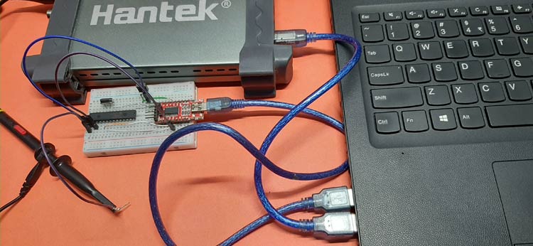
To test the circuit, the above setup is used. As you can see, we have connected an FTDI module and the oscilloscope with the USB. The FTDI module is used to get the output on the serial monitor window and, in the breadboard, we have our PIC16F886 microcontroller.
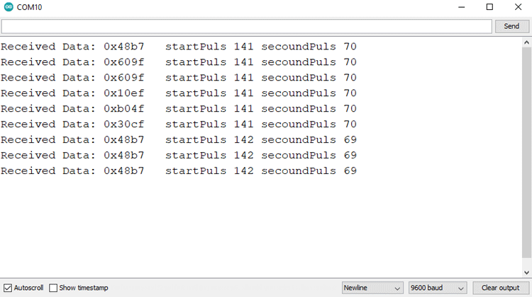
Once that was done, we uploaded the code with the help of the PICKIT2 programmer and open the serial monitor window to observe the output data with debugging information.
And sure enough, we got the data on our serial monitor window.
This marks the end of this tutorial. I hope you liked the article and learned something new. If you have any questions regarding the article, you can leave them in the comment section below or you can use our Electronics Forum.
Complete Project Code
/*
 * File:   main.c
 * Author: Debashis
 *
 * Created on January 25, 2021, 4:11 PM
 */
#pragma config FOSC = HS        // Oscillator Selection bits (HS oscillator: High-speed crystal/resonator on RA6/OSC2/CLKOUT and RA7/OSC1/CLKIN)#pragma config WDTE = OFF       // Watchdog Timer Enable bit (WDT disabled)
#pragma config PWRTE = OFF     // Power-up Timer Enable bit (PWRT disabled)
#pragma config MCLRE = OFF     // RE3/MCLR pin function select bit (RE3/MCLR pin function is MCLR)
#pragma config CP = OFF        // Code Protection bit (Program memory code protection is disabled)
#pragma config CPD = OFF       // Data Code Protection bit (Data memory code protection is disabled)
#pragma config BOREN = ON      // Brown Out Reset Selection bits (BOR enabled)
#pragma config IESO = OFF      // Internal External Switchover bit (Internal/External Switchover mode is enabled)
#pragma config FCMEN = OFF     // Fail-Safe Clock Monitor Enabled bit (Fail-Safe Clock Monitor is enabled)
#pragma config LVP = OFF       // Low Voltage Programming Enable bit (RB3/PGM pin has PGM function, low voltage programming enabled)
// CONFIG2
#pragma config BOR4V = BOR40V   // Brown-out Reset Selection bit (Brown-out Reset set to 4.0V)
#pragma config WRT = OFF        // Flash Program Memory Self Write Enable bits (Write protection off)
#define _XTAL_FREQ 16000000 // 16mhz crystal oscillator
#include <xc.h> // XC library has all the necessary functions and definations.
#include <stdio.h> // We have Included the stdio library because we are using printf for serial.
#include <pic16f886.h>
#include "uart.h" // Custom UART Library
#include "IRlib.h" // Custom IR library
#define GLOBAL_INTERRUPT INTCONbits.GIE  //1 = Enables all unmasked interrupts  0 = Disables all interrupts
#define PERIPHERAL_INTERRUPT INTCONbits.PEIE //1 = Enables all unmasked peripheral interrupts 0 = Disables all peripheral interrupts
#define TIMER0_OVERFLOW_INTERRUPT  INTCONbits.T0IE //1 = Enables the Timer0 interrupt 0 = Disables the Timer0 interrupt
#define PRESCALER_ASSIGNMENT OPTION_REGbits.PSA // 1 = Prescaler is assigned to the WDT 0 = Prescaler is assigned to the Timer0 module
#define ENABLE 1
#define DISABLE 0
#define OUTPUT 0
#define INPUT 1
#define TO_WDT 1
#define ENABLE_LOG 1
#define DISABLE_LOG 0
/* Enables all required Interrupts
 * Timer0 Overflow Interrupt is used to measure
 * the incoming pulse duration from the TSOP Sensor
 */
void INTERRUPTS_Init() {
    GLOBAL_INTERRUPT = ENABLE; // ENable Global Interrupt
    PERIPHERAL_INTERRUPT = ENABLE; // Enable Peripheral Interrupt
    TIMER0_OVERFLOW_INTERRUPT = ENABLE; // Enable Timer0 Overflow Interrupt.
}
/* The prescaler inside the PIC16f886 microcontroller
 * is either assigned to Watchdog timer or its assigned
 * to the TIMER0: For this code we have set it to WDT
 * */
void assign_prescaler() {
    PRESCALER_ASSIGNMENT = TO_WDT;
}
void init() {
    serialBegin(9600, _XTAL_FREQ); // Enable Serial with 9600 Baud )
    INTERRUPTS_Init(); // Enable all Interrupts
    assign_prescaler(); // assign prescaler
}
void main(void) {
    init(); // we call the init() function
    ir_init(); // we call the iR_init function.
    printf("System Initialized \n"); // First print statement for debugging
    while (1) {
        if (IR_SENSOR_PIN == 0) {
            ir_result(ENABLE_LOG);
        }
    }
    return;
}Comments
Hello Das,
I want the receiver sensor to be of the two-pin type (anode and cathod) and be able to receive the signal from a distance of 5 meters. How is the filter and amplifier circuit for this?
Thanks, Amir.
