

IR or infrared is one of the simplest and easiest ways to transfer data wirelessly. This property of IR makes it undetectable to the human eye and perfect for wireless communication. Apart from that IR receiver comes with a very limited range which is why it's perfect for short-range home automation projects, TV remotes, accurate range detection, RP detection, and more. For a certain project of mine, I had to decode an IR receiver signal with an STM8s microcontroller but after searching a lot I could not find any code examples or library that I could use to decode the IR signal.
So, in this tutorial, I will take you through the step-by-step process to create your own IR-based Remote Decoder library for an STM8S103F microcontroller. Apart from STM32, previously we used IR remote and IR receiver with other microcontrollers also to build many useful applications like:
- IR Remote Controlled TRIAC Dimmer Circuit
- IR Remote Controlled Home Automation using Arduino
- IR Remote Controlled Home Automation using PIC Microcontroller
- Cell Phone Controlled AC using Arduino and Bluetooth
How does IR Communication Work?
Like every other communication system out there the IR communication protocol consists of a pair of transmitters and receivers. The transmitter is an infrared LED that produces light in the infrared spectrum, while the IR receiver is a photodiode embedded with a careful design filter to remove the carrier signal and a preamplifier to produce the output signal. If you want to learn more about the basics of IR Decoding, do check out our previous article on Basic IR Transmitter and Receiver Circuit.
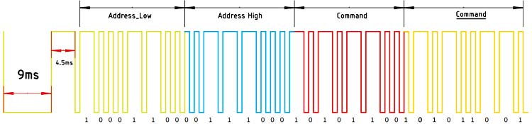
When a button on the remote is pressed, the IR LED emits infrared light consisting that data encoded with a carrier frequency. The receiver decodes that carrier signal to reproduce the data. There are various types of IR protocols out there but among them, the most common ones are NEC Remote Protocol and RC5 Remote Protocol. Today, we will take NEC as an example. To avoid interference, the NEC code uses a carrier frequency of 38KHz. The actual data is modulated using this 38KHz modulating frequency. The image below will give you the decoded data output from the receiver.
If you want to learn more about the IR Decoder, different IR protocols, and how TSOP2838 IC works you can check out our previous article about IR Remote Protocol where we discussed all the topics in detail.
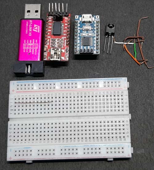
Components Required to Build Signal Decoder on STM8S103F
- STM8S103F Blue Pill Board
- STLink-V2 Programmer
- TSOP2838 IR decoder IC
- USB to UART Converter
- Breadboard
- Jumper Wires
Circuit Diagram of STM8S103 based IR Signal Decoder
The Circuit diagram for IR Remote Decoder using STM8S103F is given below. This circuit is made with very basic components so it would be easier for you to replicate.

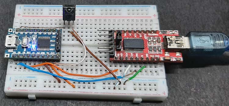
For this demonstration, we connected all the components onto a solderless breadboard using the jumper wires as per the circuit diagram. The construction of the circuit is very simple. As the pins of the microcontroller are 3.3 volts tolerant, we have powered the STM board using the 3.3V of the FTDI board. TSOP2838 IR sensor is powered from the 3.3v rail of the microcontroller and the UART converter is connected to the D5 and D6 of the board that is the RX and TX pin of the board. The final circuit looks like the image shown below.
Programming the STM8S103F Microcontroller to Decode IR Remote Data
The complete code for the STM8S103F based IR remote Decoder can be found here. For this article, we have used the ST Visual Develop IDE in conjunction with the Cosmic C Compiler to compile and upload the code. A complete breakdown and description of the code are given below. At this point, if you are having trouble setting up the ST Visual Develop IDE or Cosmic C Compiler it's highly recommended to go through our previous post on
- Getting Started with STM8S using STVD and Cosmic C Compiler.
- Serial UART Communication on STM8 using Cosmic C and STVD - Print / Read Characters and Strings
- GPIO Functions on STM8S using Cosmic C and SPL – Blinking and Controlling LED with Push Button
The objective of this project is to develop an easy-to-use library that you will be able to take in and change the GPIO and you will be good to go. We start off by including all the required libraries and we have defined the led pin which we will be using as the test led, also we defined variable data which will be used to store the data received from the IR sensor.
#include "stm8s.h" #include "stm8s_irlib.h" #define test_LED GPIOB,GPIO_PIN_5 // Onboard LED Pin int data = 0; // Variable to store IR data
Next, we have our main function. In the main function, we initialize the serial and set the baud rate to 9600. Next, we initialize the IR module by calling the ir_init() function after that we set the onboard GPIO pin as output.
main() {
Serial_begin(9600); //
Serial_print_string("Enter command \n");
ir_init(); // Init IR
GPIO_DeInit(GPIOB); // Prepare the GPIO by clearing all the register value
GPIO_Init (GPIOB, GPIO_PIN_5, GPIO_MODE_OUT_PP_LOW_SLOW); //set the GPIO as output
Next in the infinite loop, we check if the received data matches the defined data. If the data is equal turn on the LED, else turn off the LED.
while (1) {
if(data == 18615)//if received data is true {
data =0;
GPIO_WriteHigh(test_LED);// turn off the LED
}
if(data == 30855)//if received data is true {
data =0;
GPIO_WriteLow(test_LED); // turn on the LED
}
}
}
Next, we have the Interrupt Service Routine for pin D3. You need to do two things in order to work with the interrupt.
- You have to set the pin as an interrupt in the main function
- You have to declare the interrupt routine in the interrupt vector
- And define the interrupt as per the given format in the cosmic C compiler datasheet
We have already done the first part i.e we have configured the pin as an interrupt pin in the main function all that's left is to set up the interrupt vector. For that open the stm8_interrupt_vector.c file (the file is auto-generated) and add in these two lines as shown below,
/* BASIC INTERRUPT VECTOR TABLE FOR STM8 devices
 * Copyright (c) 2007 STMicroelectronics
 */
typedef void @far (*interrupt_handler_t)(void);
struct interrupt_vector {
unsigned char interrupt_instruction;
interrupt_handler_t interrupt_handler;
};
@far @interrupt void NonHandledInterrupt (void)
{
/* in order to detect unexpected events during development,
   it is recommended to set a breakpoint on the following instruction
*/
return;
}
extern void _stext();     /* startup routine */
extern @far @interrupt void EXTI3_IRQHandler (void); // Custom Interrupt Handler
struct interrupt_vector const _vectab[] = {
{0x82, (interrupt_handler_t)_stext}, /* reset */
{0x82, NonHandledInterrupt}, /* trap  */
{0x82, NonHandledInterrupt}, /* irq0  */
{0x82, NonHandledInterrupt}, /* irq1  */
{0x82, NonHandledInterrupt}, /* irq2  */
{0x82, NonHandledInterrupt}, /* irq3  */
{0x82, NonHandledInterrupt}, /* irq4  */
{0x82, NonHandledInterrupt}, /* irq5  */
{0x82, (interrupt_handler_t)EXTI3_IRQHandler}, /* irq6 (FOR PRTD3 EXTERNAL INTERRUPT) */
{0x82, NonHandledInterrupt}, /* irq7  */
{0x82, NonHandledInterrupt}, /* irq8  */
{0x82, NonHandledInterrupt}, /* irq9  */
{0x82, NonHandledInterrupt}, /* irq10 */
{0x82, NonHandledInterrupt}, /* irq11 */
{0x82, NonHandledInterrupt}, /* irq12 */
{0x82, NonHandledInterrupt},
{0x82, NonHandledInterrupt}, /* irq14 */
{0x82, NonHandledInterrupt}, /* irq15 */
{0x82, NonHandledInterrupt}, /* irq16 */
{0x82, NonHandledInterrupt}, /* irq17 */
{0x82, NonHandledInterrupt}, /* irq18 */
{0x82, NonHandledInterrupt}, /* irq19 */
{0x82, NonHandledInterrupt}, /* irq20 */
{0x82, NonHandledInterrupt}, /* irq21 */
{0x82, NonHandledInterrupt}, /* irq22 */
{0x82, NonHandledInterrupt},
{0x82, NonHandledInterrupt}, /* irq24 */
{0x82, NonHandledInterrupt}, /* irq25 */
{0x82, NonHandledInterrupt}, /* irq26 */
{0x82, NonHandledInterrupt}, /* irq27 */
{0x82, NonHandledInterrupt}, /* irq28 */
{0x82, NonHandledInterrupt}, /* irq29 */
};
Next, we will define the interrupt routine in the main file like the example below.
@far @interrupt void EXTI3_IRQHandler(void){
    data = ir_result(1);
}
Understanding the IR Library for STM8
Now that's all there is to do in the main file, and we can move on to coding the stm8s_irlib.h Header file. In this file first, we'll define all the necessary header files and the pin to which the IR sensor is connected, we also define all the required timer parameters.
#include "stm8s103_serial.h"
#include <iostm8s103.h>
#include "stm8s.h"
#define IR_SENSOR_PIN GPIOD,GPIO_PIN_3
#define IR_SENSOR_PIN_READ (GPIOD->IDR & 0b00001000) // IR sensor Pin
#define TIMER4_OVERFLOW_INTERRUPT_FLAG TIM4_SR // 1 = TMR0 register has overflowed (must be cleared in software) 0 = TMR0 register did not overflow
#define START_TIMER4 TIM4_CR1 |=(1<<0); // macro to Start timer4
#define STOP_TIMER4 TIM4_CR1 &= 0x00;//macro clear the CR1 Control reg
Next, we have defined all the necessary variables that are required to hold different parameters
int loop_counter; //variable for loop counter /*Variables to store IR Data*/ int first_start_pulse; // holds counts and verifies the first 9ms data in IR protocol int seccound_verification_puls; // holds counts and verifies the secound 4.5ms data in IR protocol uint16_t ir_received_data; //received data after decoding uint16_t ir_raw_data; // holds raw data calculated by bit shifting
Then, we have all the function prototypes used in the code. Most of those functions are pretty simple and self-explanatory. The most important function of the code are int ir_result(int debug_info), int read_data(void), and void protocol_check(void)
/*Function prototypes */ void ir_init(); void delay_us(unsigned char time); void delay_ms(unsigned int time); void timer4_init(void); void gpio_init(void); void start_timer4(void); void protocol_check(void); int read_data(void); int ir_result(int debug_info); void serial_init(void); void ir_init(void);
First, we have the ir_init() function. This function calls the other three function those are gpio_init(), timer4_init(), start_timer4()
void ir_init() { gpio_init(); // Enable Interrupt on GPIO timer4_init(); // Configure Timer 4 start_timer4(); //Start Timer4 }Next, we have our gpio_init() function as the name implies this is the function where we have configured the IR pin as Interrupt,
void gpio_init()
{
GPIO_Init(IR_SENSOR_PIN,GPIO_MODE_IN_FL_IT); // Enable Interrupt on D3 Pin
EXTI_SetExtIntSensitivity(EXTI_PORT_GPIOD, EXTI_SENSITIVITY_FALL_ONLY); // Interrupt on Falling Edge
EXTI_SetTLISensitivity(EXTI_TLISENSITIVITY_FALL_ONLY); // Interrupt on Falling Edge
}Next, we have our timer4_init() function. In this function, we have configured the timer4 to work with our timer delay and counter.
void timer4_init()
{
TIM4_SR = 0x00;// Clear Interrupt Overflow Flag
TIM4_IER = 0x00;// Disable Timer-4 Overflow Interrupt
TIM4_CR1 &= 0x00; // Clear the Timer-4 control register
TIM4_CR1 |=(1<<2); // Update Request Source Generates Interrupt
TIM4_EGR = 0x00;// Clear Event Generation Register
TIM4_CNTR = 0x00;// Set Counter to zero, We need Counter for Delay
TIM4_PSCR = 0x01;// Prescaler -> Clock/2 16/2 ->8MHz
TIM4_IER = 0x01; // Enable Timer4 Interrupt
TIM4_CR1 |=(1<<0); // Start Timer4
}Next, we have our start timer function. This function only starts the time.
void start_timer4()
{
    enableInterrupts();// Enable Global Interrupt
    TIM4_IER = 0x01; // Enable Timer4 Interrupt
    TIM4_CR1 |=(1<<0); // Start Timer4
}
Next, we have the ir_result(int debug_info) function which gives back the IR result when it is called. Inside the function, another function that gets a call is the protocol_check() function. Remember the first 9ms start pulse followed by a 4.5ms pulse. The protocol_check() function checks that and returns. Once it returns, it populates the structure with the timer counter value. If the timer counter value is true then the read_data() function gets a call inside the read data function. We construct the binary data from the received pulses and once that is done, we populate the variable with the received value and finally, it gets printed,
int ir_result(int debug_info) {
        GPIO_Init(IR_SENSOR_PIN,GPIO_MODE_IN_FL_NO_IT);    //configure thepin as standard IO
        protocol_check(); // call protocol_check function
    /*inside the protocol check function the timer counter checks the pulse width
        if it is greater than 141 and less than 145 the statement is true.
        you can do this calculation by taking the datasheet as reference*/
    if (first_start_pulse >= 33 && first_start_pulse <= 38) {
        if (seccound_verification_puls >= 16 && seccound_verification_puls <= 21) {
            read_data(); //call the function and get first 16 bit
            ir_received_data = read_data(); //call the function again and get second 16 bit
            if (debug_info) { //if set to 1 then print the data if 0 don't print the data
                  Serial_print_int(ir_received_data);
                                Serial_print_string("\n");
            }
        }
}
    gpio_init(); // reconfigure the GPIO as interrupt
    start_timer4();// because of the delay_us function the interrupt gets turned off we need to turn the interrupt on for a smooth operation
    return ir_received_data;
}
Finally, we have two of our delay functions that produce accurate delay.
/* Timer Based delay_us Function */
void delay_us(unsigned char time){
  TIM4_EGR |= (1<<0); // Set event generation register
  TIM4_CNTR = 0; // Force set counter to zero
  TIM4_CR1 |= (1<<0); // Enable Timer4 Control Register
  while(TIM4_CNTR<time);
  TIM4_CR1 &= ~(1<<0); // Disable Timer4 Control Register
  TIM4_SR &= ~(1<<0); //clear interrupt flag
}
/*delay_ms Function derived from delay_us Function */
void delay_ms(unsigned int time){
  time *= 10;
  while(time--);
  delay_us(100);
}
STM8S103F Based IR Decode Testing
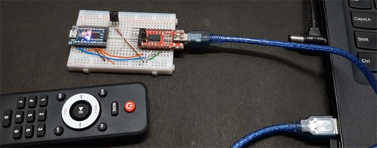
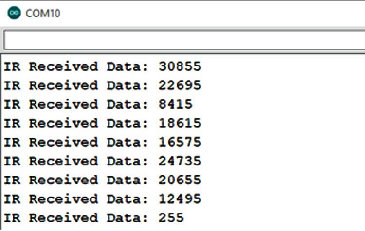
To Test the circuit the above setup is used. As you can see, we have connected the circuit according to the schematic, where the FTDI module is distributing power from the USB port of the laptop, and also, its responsible for printing the output data to the serial monitor window.
Once that was done, we uploaded the code with the help of the ST-Link V2 programmer and open the serial monitor window to observe the output data with debugging information. A screenshot of the serial monitor window is shown below.
This marks the end of this tutorial. I hope you liked the article and learned something new. If you have any questions regarding the article, you can leave them in the comment section below or you can use our Electronics Forum
Complete Project Code
/* MAIN.C file
 *
 * Copyright (c) 2002-2005 STMicroelectronics
 */
#include "stm8s.h"
#include "stm8s_irlib.h"
#define test_LED GPIOB,GPIO_PIN_5 // Onboard LED Pin
int data = 0; // Variable to store IR data
main(){
            Serial_begin(9600); //
            Serial_print_string("Enter command \n");
            ir_init(); // Init IR
            GPIO_DeInit(GPIOB); // Prepare the GPIO by clearing all the register value
            GPIO_Init (GPIOB, GPIO_PIN_5, GPIO_MODE_OUT_PP_LOW_SLOW);  // set the GPIO as output
            while (1) {
                     if(data == 18615)//if received data is true
                     {
                        data =0;
                        GPIO_WriteHigh(test_LED);// turn off the LED
                     }
                     if(data == 30855)//if received data is true
                     {
                      data =0;
                      GPIO_WriteLow(test_LED); // turn off the LED
                     }
            }
}

@far @interrupt void EXTI3_IRQHandler(void){
            data = ir_result(1);
}
Considero que es de gran utilidad la información que publican, esto contribuye al desarrollo de la tecnología.
Felicitaciones