

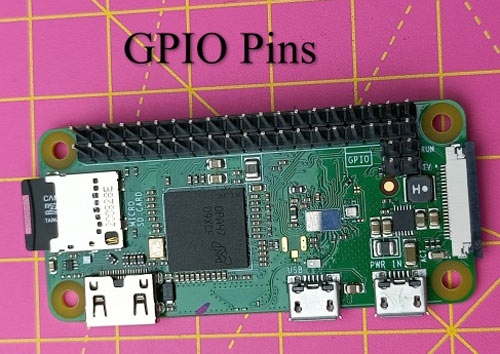
In our previous tutorial Getting Started with the RASPBERRY PI ZERO, we had an overview Raspberry Pi zero W and setup the Pi Zero. In this tutorial we are going to design a simple LED circuit and control it with the Raspberry Pi Zero W by connecting the circuit to its GPIO pins. So lets discuss the basics of the GPIO (general purpose input output) pins and learn how to get started with physical computing and GPIO using Python programming.
What are GPIO Pins?
GPIO (General Purpose Input Output) is a standard interface for digital input and output found on microcontrollers and SBCs. It enables these devices to control external components such as rotors and IR transmitters (output) as well as receive data from sensor modules and switches (input) (input). In essence, GPIO allows our Raspberry Pi to communicate with a wide range of external components, making it useful for projects ranging from a weather station to a self-driving robot. Software configurations will be necessary for GPIO pins to work.
GPIO Capability of Raspberry Pi Zero W
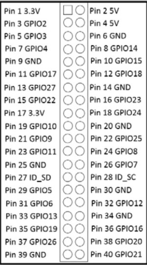
GPIO pins are general-purpose pins that can be used to switch external devices on and off, such as LEDs. The GPIO header on your Raspberry Pi has a total of 40 GPIO pins. On the Raspberry Pi Zero W, pins 1 and 17 supply 3.3 volts; pins 2 and 4 supply 5 volts, while pin 9, 25, 39, 6, 14, 20, 30, and 34 are all attached to ground. Here, you can see a list of all 40 pins of Raspberry Pi Zero W and their connection to Raspberry Pi zero. The remaining pins have different functions. Each pin on the 40-pin header has a specific purpose. In the table below, the various categories are described.
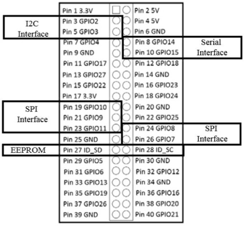
Power- 5V and 3.3V pins are used to give 5V and 3.3V power to external module.
UART- For serial communication, UART (Universal Asynchronous Receiver/Transmitter) pins are utilized.
I2C - I2C pins are used to connect and communicate with external modules that are I2C compliant.
SPI - Hardware communication is also done via SPI (Serial Peripheral Interface Bus) pins, although with a different protocol.
GND- GND (Ground) pins are pins in your circuits that offer electrical grounding.
In the upcoming Raspberry Pi zero W tutorials, you'll learn more about these dedicated functions. In the below image, you can see some important functions that have been assigned to the pin.
LED blinking using Raspberry Pi Zero W
Here, we are going to blink two LEDs using GPIO pins. The simplest connection that you can make to the GPIO (general purpose input output) on Raspberry Pi zero w is to connect to a pin so that you can send a simple digital output voltage. You'll do this by lighting an LED with the GPIO IO pins. You’ll need following hardware to complete the project:
- 1 x Raspberry Pi zero W
- 1 x bread board
- 2 x LED light
- 2 x 330 ohm resistor
- 4 x male to female jumper wire
Circuit Diagram
In the image below you can see the circuit diagram of the LED blinking hardware setup.

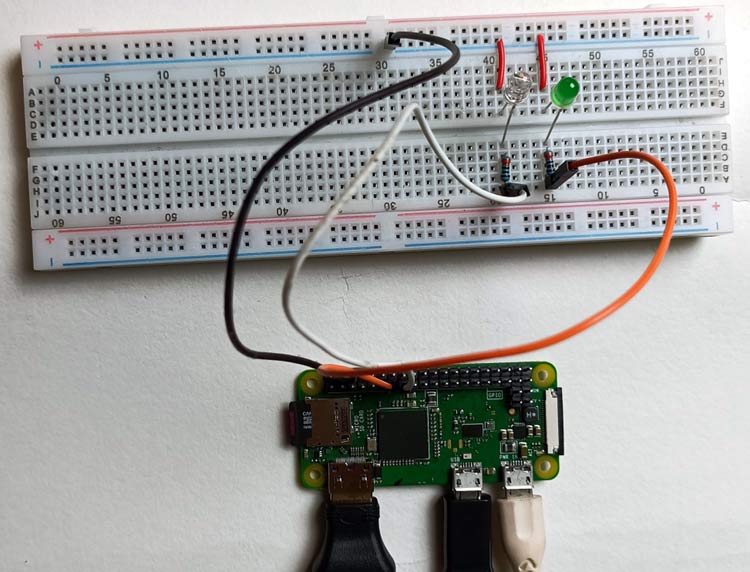
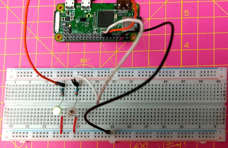
Here, we have two LEDs, the positive terminal of red LED is connected with GPIO 27 (pin 13) and positive terminal of yellow LED is connected with GPIO 22 (pin 15) and negative terminal of both LEDs are connected to ground pin (pin 6) of Raspberry Pi zero W. We have used two 220- ohm resistors to drop voltage at positive terminal of LED. You can see actual hardware connection in below image.
Code explanation for Blinking LED using Pi zero W
Here, we are going to explain all code line by line. First, you'll need to boot up the Raspberry Pi Zero. Then you need to log in and open a terminal window. Now, you need to update package version of Raspberry Pi using below command.
sudo apt-get update
You have to install the RPi.GPIO package. This package is necessary to access the GPIO pins of Raspberry Pi zero W. You can install this package in raspberry pi zero W using the below command.
sudo apt-get install rpi.gpio
Now, you can write the Python code for blinking LED in terminal window.
#!/user/bin/python - This line lets you run this code without typing Python before the filename
import RPi.GPIO as io - This will allow you to import the RPi.GPIO library, allowing you to control the GPIO pins.
import time - Several time-based functions are available in the time library. In this case, you'll use it to stop the code for a few seconds.
io.setmode(io.BCM) - This changes the GPIO pins' specification mode to Broadcom SOC channel number (BCM). This implies that instead of specifying the physical pin numbers, you'll use the GPIO numbers for the pins you want to control.
led1 = 27 - it sets the value 27 to the led1 variable.
led2 = 22 - It sets the value 22 to the led2 variable.
io.setup(led1, io.OUT) - The GPIO pin 27 is now configured to an output control.
io.setup(led2, io.OUT) -The GPIO pin 22 is now configured to an output control.
while 1 - This locks you into a never-ending loop. To stop the code, press Ctrl + C on your keyboard.
io.output(led1, True)- On led1, this will provide a 3.3 volt signal (this is GPIO 27)
io.output(led2, True) - On led1, a 3.3 volt signal will be produced as a result of this (this is GPIO 22).
time.sleep(1): This will cause a one-second halt in the program.
io.output(led1, False) -On led1 (GPIO 27), this will produce 0 volts.
io.output(led2, False)- On led2 (GPIO 22), this will produce 0 volts.
time.sleep(1)- This causes a one-second halt in a program.
Code:
#!/user/bin/python
import RPi.GPIO as io
import time
io.setmode(io.BCM)
led1 = 27
led2 = 22
io.setup(led1, io.OUT)
io.setup(led2, io.OUT)
while 1
io.output(led1, True)
time.sleep(1)
io.output(led1, False)
io.output(led2, True)
time.sleep(1)
io.output(led2, False)
time.sleep(1)
Save the program named as led.py and type python led.py to run the program in terminal window. Now, you will see that the two LEDs starts blinking at one-second intervals. Here, you can see image of blinking LED.
This is how you can blink LED using Raspberry Pi zero W. This was a basic 'getting started' guide for understanding GPIO pins. In our next tutorials, we are going to interface different sensors camera and LCD display with Raspberry Pi zero. Hope you enjoyed the project and learned something useful. If you have any questions, please leave them in the comment section below or use our forum to start a discussion on this.
Complete Project Code
#!/user/bin/python
import RPi.GPIO as io
import time
io.setmode(io.BCM)
led1 = 27
led2 = 22
io.setup(led1, io.OUT)
io.setup(led2, io.OUT)
while 1
io.output(led1, True)
time.sleep(1)
io.output(led1, False)
io.output(led2, True)
time.sleep(1)
io.output(led2, False)
time.sleep(1)
Comments
Hi, The original code didnt…
Hi, The original code didnt work for me either. However, I edited as below which then worked fine by removing the While 1 comment and adding in the While Loop. After while True, the following lines need to be idented.
Hope this helps
#!/user/bin/python
import RPi.GPIO as io
import time
io.setmode(io.BCM)
led1 = 27
led2 = 22
io.setup(led1, io.OUT)
io.setup(led2, io.OUT)
# While Loop
while True:
io.output(led1, True)
time.sleep(1)
io.output(led1, False)
io.output(led2, True)
time.sleep(1)
io.output(led2, False)
time.sleep(1)

Hi, i try it but it have error with command while 1